Coating equipment applied to high-performance electricity-resistant coating of metal product

A technology for coating equipment and metal products, applied in the direction of spraying devices, etc., can solve the problems of no fixing of metal products, positional deviation of coated metal products, etc.

Active Publication Date: 2021-08-20
南通安泰新材料科技有限公司
View PDF7 Cites 0 Cited by
  • Summary
  • Abstract
  • Description
  • Claims
  • Application Information

AI Technical Summary

Problems solved by technology

[0004] At present, when the coating equipment smears the metal, it usually moves the metal product to be processed to the bottom of the nozzle through the transmission device, but when processing, the metal product to be p

Method used


Image

  • Coating equipment applied to high-performance electricity-resistant coating of metal product
  • Coating equipment applied to high-performance electricity-resistant coating of metal product
  • Coating equipment applied to high-performance electricity-resistant coating of metal product

Examples


Embodiment 1

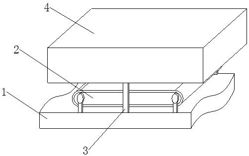
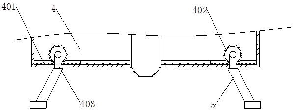
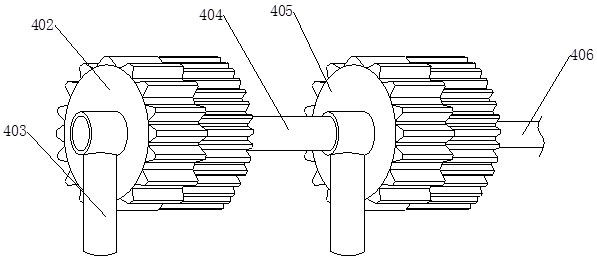
[0026] A high-performance resistive coating coating equipment applied to metal products, including a base 1, a conveyor belt 2 and a support column 3, the conveyor belt 2 is arranged above the base 1, and the base 1 is fixed on the front and rear sides of the conveyor belt 2 Connected to the support column 3, the end of the support column 3 away from the base 1 is provided with a fixed frame 4 that can be limited, and the inner bottom of the fixed frame 4 is provided with four slide rails 401, and the inside of the fixed frame 4 is located at the bottom of the slide rail 1 401. The side near the center is provided with slide rail three 409, slide rail one 401 and slide rail three 409 are staggered and connected front and back, the bottom ends of slide rail one 401 and slide rail three 409 are provided with tooth holes, and the inside of the fixed frame 4 is fixed A slide rail 2 408 is connected, and two slide blocks 407 are embedded inside the slide rail 2 408. The side of the ...

Embodiment 2

[0033] The difference between this embodiment and Embodiment 1 is that every two slide rails 401 are on the same plane and straight line.

[0034] Wherein: when the driven gear 402 and the driving gear 405 are moving along the slide rail one 401, the moving positions of the driven gear 402 and the driving gear 405 are the same, driving the fixed plate 5 to move, so that the fixed plate 5 is moving more convenient time.

[0035] The difference between the present embodiment and the first embodiment is that the surface of the moving plate 503 away from the moving rod 502 is uneven and is provided with a rubber layer.

[0036] Wherein: when the moving plate 503 is in contact with the metal product, increase the frictional force between the moving plate 503 and the metal product, so that when the metal product is fixed, it is more stable and reduces the displacement of the metal product during processing Phenomenon.

[0037] The difference between this embodiment and Embodiment 1 ...


PUM


Abstract

The invention provides coating equipment applied to high-performance electricity-resistant coating of a metal product. The coating equipment comprises a base, a conveying belt and a supporting column. Fixing plates, a driven gear and a driving gear are installed, the two fixing plates form a splayed shape, when the metal product is machined, one motor rotates clockwise, the other motor rotates anticlockwise, the driven gear and the driving gear on the two sides are driven to move along a first sliding rail to a third sliding rail, when the driven gear and the driving gear rotate, the ends, away from a fixing rod, of connecting rods are perpendicular to the ground through a bearing under the gravity action of the connecting rods and the fixing plates, and the horizontal distance between the two connecting rods is gradually decreased, so that the distance between the connecting plates at the bottom ends of the two fixing plates is gradually decreased; and the connecting plates approach the metal product in the moving process until the side faces of the two connecting plates make contact with the metal product, so that the metal product is fixed, and machining of the metal product is facilitated.

Description

technical field [0001] The invention relates to the technical field of intelligent manufacturing equipment, in particular to a coating equipment for high-performance resistive coating applied to metal products. Background technique [0002] With the development of science and technology, metal products are used more and more widely. In order to make metal products safer and more durable during use, coating equipment is usually used to coat the outside of metal products, so as to coat the outside of metal products. Protect. [0003] Among them, after searching, it is found that there is a patent No. CN201120201331.3 metal powder coating equipment. Compared with traditional manual coating, this new type of coating equipment is not only faster and more convenient, but also easier to control the thickness and uniformity of the film. degree, to achieve the effect of automatic spraying, and through the recycling of the second storage barrel, to achieve environmental protection be...

Claims


Application Information

Patent Timeline
IPC IPC(8): B05B13/02
CPCB05B13/0285
Inventor 常代展王雷谭明强
Owner 南通安泰新材料科技有限公司
Why Eureka
Try Eureka