Stamping die with discharging function for automobile precision part

A technology for precision parts and stamping dies, which is applied in the field of stamping dies for automobile precision parts, can solve the problems of time-consuming and laborious, manual discharge, etc., to achieve stamping protection, facilitate automatic discharge, and reduce labor costs.

Pending Publication Date: 2021-08-20
长兴恒兴精工科技有限公司
View PDF0 Cites 0 Cited by
  • Summary
  • Abstract
  • Description
  • Claims
  • Application Information

AI Technical Summary

Problems solved by technology

[0004] The purpose of the present invention is to provide a stamping die for automotive precision parts with the function of discharging, so as to solve the problem that manual discharging is required in the above-mentioned background technology, which is time-consuming and labor-intensive.

Method used


Image

  • Stamping die with discharging function for automobile precision part
  • Stamping die with discharging function for automobile precision part
  • Stamping die with discharging function for automobile precision part

Examples


Embodiment 1

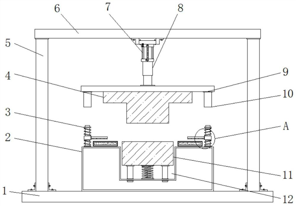
[0021] Example 1: See Figure 1-4 , a stamping die for automotive precision parts with a discharging function, comprising a base 1, two sets of columns 5 are fixedly welded on both sides of the top of the base 1, a horizontal plate 6 is fixedly welded on the top of the column 5, and the bottom of the horizontal plate 6 end is fixedly connected with a cylinder 7, the output end of the cylinder 7 is fixedly connected with a telescopic rod 8, the top of the base 1 is fixedly connected with a workbench 2, the bottom end of the telescopic rod 8 is fixedly connected with a fixed plate 9, and the bottom end of the fixed plate 9 is fixed The upper mold 4 is connected, the two sides of the top of the workbench 2 are fixedly connected with the limit column 3, the inside of the workbench 2 is provided with a groove 12, the inside of the groove 12 is placed with a lower mold 11, and one end of the top of the workbench 2 is set There is a push plate 13;

[0022] see Figure 1-4 , a stamp...

Embodiment 2

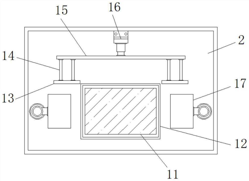
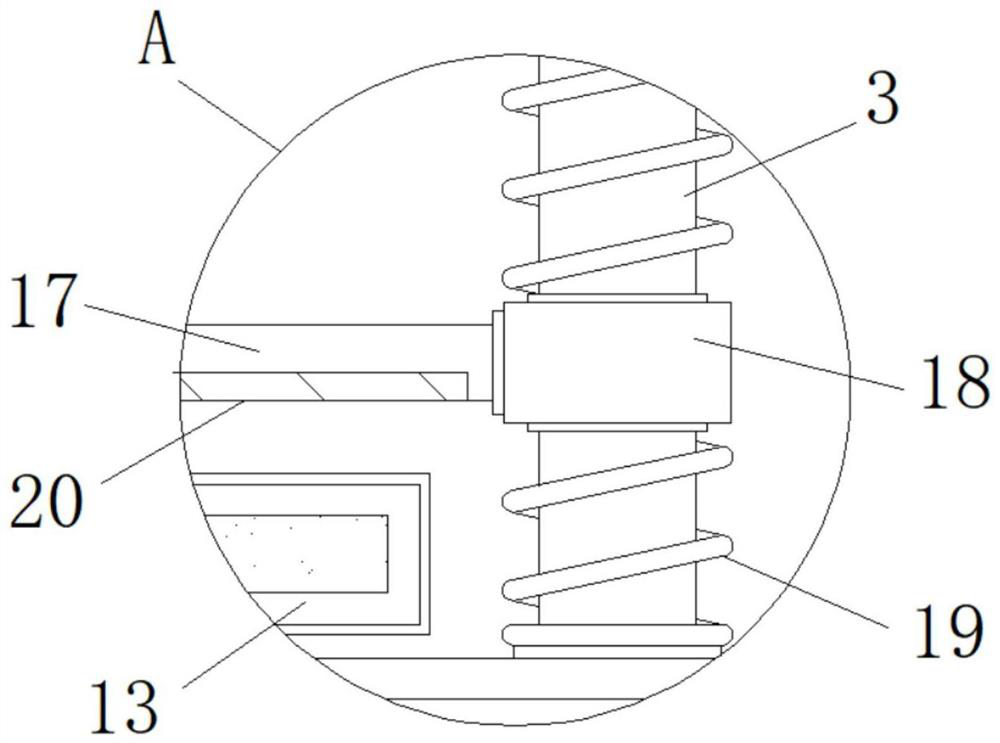
[0024] Embodiment 2: the limit spring 19 is socketed on the outside of the limit post 3, the slide sleeve 18 is connected to the outside move of the limit post 3, one side of the slide cover 18 is fixedly connected to the limit plate 17, and the limit plate 17 The bottom end is fixedly connected with a rubber pad 20, and the two sides of the bottom end of the fixed plate 9 are fixedly connected with two sets of sleeves 10;

[0025] The limit post 3 is provided with two groups, and the sliding sleeve 18 outside the limit post 3 is arranged between the limit springs 19, and the limit spring 19 can drive the slide sleeve 18 to move together during the movement;

[0026] Specifically, such as figure 1 and image 3 As shown, when an automobile part is placed above the lower mold 11, the middle of the part will be stamped and bent. During the stamping process, the bushings 10 on both sides of the upper mold 4 are set on the outside of the stopper column 3 and pressed down to move t...

Embodiment 3

[0027] Embodiment 3: two sets of limit rods 21 are fixedly connected to both sides of the bottom end of the lower mold 11, a return spring 22 is fixedly connected between the lower mold 11 and the groove 12, and two sets of through holes 23 run through the inside of the groove 12. The outer dimension of the lower mold 11 is smaller than the inner dimension of the groove 12, and the limit rod 21 at the bottom of the lower mold 11 is embedded in the inside of the through hole 23;

[0028] Specifically, such as figure 1 and Figure 4 As shown, in the process of stamping the lower mold 11 by the upper die 4, firstly, the casing 10 first contacts the limit post 3 and exerts pressure on the limit spring 19 outside the limit post 3 to cause the spring to retract. When the spring retracts, it will Provide back impact force and buffer force, and then during the downward movement of the lower mold 11, the limit rod 21 at the bottom of the lower mold 11 is inserted into the through hole...


PUM


Abstract

The invention discloses a stamping die with a discharging function for an automobile precision part. The stamping die comprises a base, two sets of stand columns are fixedly welded to two sides of the top end of the base, a transverse plate is fixedly welded to the top ends of the stand columns, an air cylinder is fixedly connected to the bottom end of the transverse plate, a telescopic rod is fixedly connected to the output end of the air cylinder, and the top end of the base is fixedly connected with a workbench. According to the stamping die with the discharging function for the automobile precision part, through push plates, supporting rods, a connecting plate, an electric push rod and a reset spring, the part is ejected to the surface of the workbench by a lower die after being stamped, at the moment, the electric push rod pushes the supporting rods in the direction of the part, the push plates at one end of the supporting rods push the part and push the part out of the device, then the electric push rod drives the push plates to retract to the original position, therefore, automatic discharging is realized, labor expenditure is reduced, meanwhile, follow-up normal stamping machining cannot be affected, and the problem that manual discharging is needed, so that time and labor are wasted is solved.

Description

technical field [0001] The invention relates to the technical field of automobile parts processing, in particular to a stamping die for automobile precision parts with a material discharging function. Background technique [0002] Auto parts refer to the parts that make up the car. The processing of auto parts mainly adopts stamping method, and stamping needs to use stamping dies. Stamping dies are a special process equipment for processing materials into parts in cold stamping processing, but the existing There are still some deficiencies in the use of stamping dies for auto parts that need to be improved. [0003] For example, during the stamping process of the stamping die, the internally processed parts are prone to shift, break or pop up, which is easy to accidentally injure the staff and cause unnecessary losses, or the stamped parts need to be manually taken out one by one, not only It wastes time and reduces the efficiency of processing, so we develop a stamping die...

Claims


Application Information

Patent Timeline
Patent Type & Authority Applications(China)
IPC IPC(8): B21D37/10B21D45/04B21D53/88B21D43/00F16F15/067
CPCB21D37/10B21D43/003B21D45/04B21D53/88F16F15/067
Inventor 寇军
Owner 长兴恒兴精工科技有限公司
Why Eureka
Try Eureka