An automatic laying method

An automatic and laying technology, applied in the direction of climate sustainability, final product manufacturing, weight reduction, etc., can solve the problems of layer-by-layer stacking, low laying efficiency, adhesion and pulling of the anvil knife and the surface of the tape, etc. Achieve the effects of improving production efficiency, ensuring laying effect, and saving laying time

Active Publication Date: 2022-07-08
CHANGSHA UNIVERSITY OF SCIENCE AND TECHNOLOGY
View PDF0 Cites 0 Cited by
  • Summary
  • Abstract
  • Description
  • Claims
  • Application Information

AI Technical Summary

Problems solved by technology

[0005] 1. The automatic laying technology of the prior art is to lay the prepreg tape layer by layer on the surface of the mold. After laying several layers, the composite material component reaches a certain thickness. Therefore, for laying multi-layer prepreg tape The mold can only be stacked layer by layer, and the laying efficiency is low
[0006] 2. At the end of laying each path, the laying mechanism must go back and forth or turn around to re-lay the previous laying path or lay the next path. Therefore, during the automatic laying process, the laying mechanism needs to Multiple round trips or U-turn laying, wasting a lot of time
[0007] 3. The existing cutting method is the contact cutting of the cutting board and the anvil knife. Since the strip material is moving during the laying process, the contact cutting is easy to cause adhesion and pulling of the anvil knife and the surface of the strip material, which will cause unnecessary damage to the strip material. The tension will affect the laying effect of the tape at the moment of cutting

Method used


Image

  • An automatic laying method
  • An automatic laying method
  • An automatic laying method

Examples


Embodiment Construction

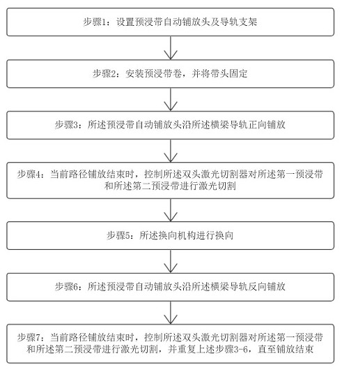
[0046] As shown in the figure: an automatic laying method, characterized in that: comprising the following steps:

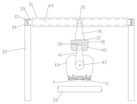
[0047] Step 1: Set up the automatic prepreg tape placement head and the guide rail bracket: the guide rail bracket includes two U-shaped support columns 30, rolling beams 31 and a placement head fixing device, and the two U-shaped support columns 30 are symmetrically arranged on the On both sides of the automatic prepreg tape laying head, the two ends of the rolling beam 31 are respectively connected with the tops of the two U-shaped support columns 30, and the rolling beam 31 is provided with a beam guide 44 inside. The outer side of the automatic prepreg tape laying head is provided with a cover 43, the cover 43 is connected with the rolling beam 31 through the laying head fixing device, and the second rolling wheel 35 of the laying head fixing device can be in the beam guide 44. Rolling, the automatic prepreg tape laying head includes a feeding mechanism, a la...


PUM


Abstract

An automatic laying method includes the following steps: step 1: setting an automatic laying head and a guide rail bracket for a prepreg tape, step 2: installing a prepreg tape roll and fixing the tape head, step 3: automatically laying the prepreg tape The laying head is placed along the beam guide in the forward direction, step 4: when the laying of the current path is completed, the double-head laser cutter is controlled to perform laser cutting on the first prepreg tape and the second prepreg tape, Step 5: The reversing mechanism performs reversing, Step 6: The automatic prepreg tape laying head is reversely laid along the beam guide rail, Step 7: When the laying of the current path is completed, the double-head laser is controlled The cutter performs laser cutting on the first prepreg tape and the second prepreg tape, and repeats the above steps 2-5 until the laying is completed. The automatic laying method does not require single layer-by-layer laying, which greatly improves the production efficiency, and at the same time does not need to return or turn around in an empty way, which saves the laying time.

Description

technical field [0001] The invention relates to the field of automatic laying, in particular to an automatic laying method. Background technique [0002] The automatic laying technology has the characteristics of high efficiency, high quality, high reliability and low cost, and is especially suitable for the manufacture of large-sized components, which reduces the number of assembled parts, saves manufacturing and assembly costs, and greatly reduces the waste rate of materials. It is widely used in the manufacture of aerospace high-performance composite structures. [0003] The automatic laying technology uses the prepreg tape as the raw material. After heating, it is directly laid on the surface of the mold or the upper layer of the prepreg tape under the action of the pressing roller to realize the automatic forming of the composite material laying. [0004] Disadvantages of the prior art: [0005] 1. The automatic laying technology of the prior art is to lay the prepreg...

Claims


Application Information

Patent Timeline
Patent Type & Authority Patents(China)
IPC IPC(8): B29C70/38B29C70/54
CPCB29C70/386B29C70/388B29C70/54B29C70/545Y02T50/40
Inventor 张鹏冯文明高远缑建杰蔡礼超邓连辉
Owner CHANGSHA UNIVERSITY OF SCIENCE AND TECHNOLOGY
Why Eureka
Try Eureka