Very simple configuration spacecraft and space rendezvous control method thereof

A space rendezvous and spacecraft technology, which is applied in the direction of space navigation aircraft, aircraft, space navigation equipment, etc., can solve the problem that it is not suitable for installing thrusters, increases the volume, weight, and power consumption of spacecraft, and cannot deal with single thruster failures. And other issues

Pending Publication Date: 2021-08-20
INNOVATION ACAD FOR MICROSATELLITES OF CAS +1
0 Cites 0 Cited by

AI-Extracted Technical Summary

Problems solved by technology

[0003] However, there are some obvious deficiencies in the above-mentioned technical solutions: not all sides of the spacecraft can deploy thrusters, for example, the surface where the solar cell array is installed and the surface where cameras and optical sensors are deployed are not suitable for installing thrusters
Moreove...

Method used

In the simulation, reducing the propulsion acceleration (reducing the thrust size or increasing the mass of the star) and reducing the guidance control period can improve the guidance control accuracy, and the one-shot delay execution of the control command has less influence on the rendezvous and approach control results, and the simulation results are as follows Figure 3-Figure 7 shows. The above simulation results show that: through the extremely simplified thruster layout scheme, the perfect decoupling of the translation and rotation of the star can be guaranteed; and the guidance and control ...

Abstract

The invention relates to the technical field of spacecraft space rendezvous control, and provides a very simple configuration spacecraft and a space rendezvous control method thereof. The spacecraft comprises a laser range finder, a camera, inter-satellite communication equipment and first to sixth thrusters. Through a thruster layout scheme with extremely simple configuration, perfect decoupling of translation and rotation of the star can be ensured. And smooth convergence of each channel of the translation channel can be ensured by adopting a guidance control scheme based on a phase plane. In addition, scheduling control of each thruster is carried out based on a thruster hybrid scheduling algorithm, the translational motion control effect in the rendezvous approaching process of the spacecraft is ensured, and a good tail end docking condition is created. According to the method, free control over three axes and six directions of translation of the spacecraft can be achieved under the condition of extremely simple configuration of the thruster, high control precision can be achieved, on-satellite space and manufacturing and operating cost can be saved, meanwhile, single faults of the thruster can be handled, and the method has a higher practical value.

Application Domain

Cosmonautic vehiclesCosmonautic component separation

Technology Topic

SatelliteLaser ranging +8

Image

  • Very simple configuration spacecraft and space rendezvous control method thereof
  • Very simple configuration spacecraft and space rendezvous control method thereof
  • Very simple configuration spacecraft and space rendezvous control method thereof

Examples

  • Experimental program(1)

Example Embodiment

[0055] It should be noted that each component in the drawings may be exaggerated for illustrative description, and it is not necessarily a ratio. In each of the drawings, the same components as the same or functionally are equipped with the same reference numerals.
[0056]In the present invention, unless otherwise indicated, "arranged" "," arranged above "and" arranged above "and" arranged above "did not exclude the case where the intermediates were present between the two. Further, "arranged or above" only indicates the relative positional relationship between the two components, and in a certain case, if it is inverted the product direction, it can also be converted to "arranged under or below", but also NS.
[0057] In the present invention, each embodiment is intended to illustrate the aspects of the invention without being construed as limiting.
[0058] In the present invention, unless otherwise indicated, the quantifier "one", "a" and "one" does not exclude the scene of the plurality of elements.
[0059] It should also be noted herein, in the embodiment of the present invention, in order to clearly, only some of the components or components may be shown, but one of ordinary skill in the art will appreciate that under the teachings of the present invention, Scenes need to add the required components or components. In addition, features in different embodiments of the invention may be combined with each other unless otherwise stated. For example, a feature in the first embodiment can be replaced in the first embodiment, and the resulting embodiments are also collected in the disclosure or document range of the present application.
[0060] It should also be noted here that "the same", "equal", "equal", "equal", etc., is not intended to be absolute equal, but to allow a certain reasonable error, that is, the Wording also covers "basically the same", "basically equal", "basically equal". In this kind, in the present invention, the terms "perpendicular to", "parallel to", and the like, which are "parallel to", and "substantially parallel to".
[0061] Further, the number of the steps of each method of the present invention does not define the execution order of the method steps. Unless otherwise stated, each method step can be performed in different order.
[0062] The present invention will be further illustrated with reference to the accompanying drawings.
[0063] One embodiment of the present invention proposes a minimally arrangement spacecraft, including: laser range finder, camera, star communication device, and first to sixth thrusters. Among them, the laser range finder can measure the star spacing between spacecraft. The camera can measure the star spacing vector azimuth between the spacecraft. Star communication devices can transmit scheduled data between spacecraft. The first to sixth thrusters can perform thrust operation to promote the minimalizing configuration spacecraft motion.
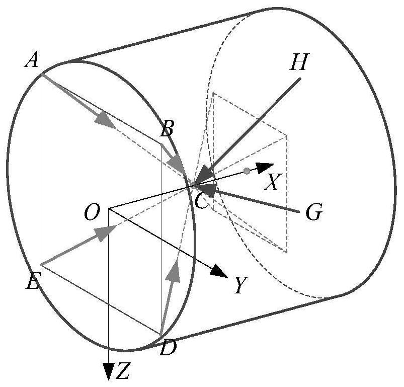
[0064] figure 1 A thrust layout and thrust line of a generic spacecraft is shown in one embodiment of the present invention. like figure 1 As shown, the thrust line of the first to sixth thrusters (A, B, D, E, G, H) passes through the centroid C, the first to fourth thrusters (A, B, D, E) in the spacecraft The anti-flight direction surface (-X surface) of the spacecraft is X-type pairing, and the sixth thrust (G, H) is on the flight direction surface (+ x surface) of the spacecraft The flight direction (+ x-axis direction) symmetrical arrangement of the spacecraft. In the absence of a thrust failure, the first to sixth thrusters (A, B, D, E, G, H) can operate according to the normal mode, when any of the thrusters in A, B, D, and E When the fault can be done by the ABDE Troubleshoot mode, when the G and H is fails, you can work according to the ghm failure mode. Through the arrangement of the above thrust, the mita-shaped three-axis six-to-sync-synergistic sense can be realized, and the flat control of the thrust single-weight failure can be achieved.
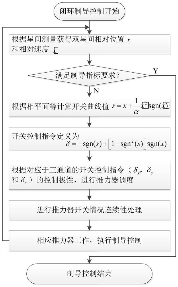
[0065] figure 2 A flowchart of spacecraft space conversions control is shown in one embodiment of the present invention. like figure 2 As shown, the spacecraft is closely intersected approximation in the full-day, all state. Specifically, include the following steps:
[0066] Step 1, collect the relative motion parameters between the schema, including:
[0067] The spacecraft can perform the relative position motion parameters by the laser range finder to perform relative position motion parameters, or by bisens of GNSS (Navigation Satellite System) data (transmitted to the active star through the star communication device). The collected relative position motion parameters can be filtered by the navigation filter algorithm, and the burrs are removed and the relative speed parameters are determined. The simplest handling method is:
[0068]
[0069]
[0070] Where X m Indicates the current measured value of the star spacing. The star spacing vector estimate of the star k-1 and the kth moment, respectively. Indicates that the star spacing change rate vector, n indicates that the normal number of less than 1 and the DT representation of the sampling period. However, those skilled in the art will appreciate that the processing mode of filtering processing is not limited to the above example, and those skilled in the art can perform filtering processing according to actual selection of other filter algorithms such as Kalman filter algorithm.
[0071] It is also worth noting that considering the characteristics of the spacecraft rendezvous task, the relative motion component in the lateral direction and the normal direction can be negative, but the relative motion state component in the track direction can only be negative.
[0072] Step 2, for the current shot of the star spacing vector and the star spacing change rate vector, determine if the guidance process is completed, including:
[0073] If the star spacing vector and the star spacing change rate vector meet the guidance process end conditions, the jump step 8; otherwise, the process proceeds to step 3.
[0074] Step 3: Determining the relative switch state parameters of the flat channel for the flat channel of the spacecraft, wherein the flat channel includes a spacecraft X \ y \ z-axis flat channel in the XYZ three-axis direction, including:
[0075] For i-axis flat channel, in the flat channel star spacing x i And I-axis flat channel star spacing change rate A parabolic switched curve is constructed on the phase plane constituting, which is expressed as the formula:
[0076]
[0077] I = x, y, z
[0078] Among them, α i Indicates the opening coefficient of the parabolic switch curve;
[0079] According to I axis flat channel star spacing x i And I-axis flat channel star spacing change rate Determine the relative switch status parameter S of the I axis flat channel i , Expressed as the formula:
[0080]
[0081] Step 4, according to the relative switch state parameter S i Determine the control switch command Δ corresponding to the I axis flat channel i , Expressed as the formula:
[0082] δ i = -SGN (s i ) + [1-SGN 2 (s) i )] SGN (X i )
[0083] Among them, the control switch command Δ i Can be δ x ,δ y Or δ z. Δ i Only the third state of 0 is 0 when the phase of the motion state is located in the phase flat coordinate origin; slightly, the state of this minimal probability, the control switch command δ i A total of -1 and 1 states.
[0084] Step 5, according to the control switch instruction δ corresponding to the three-way channel x ,δ y And δ z , Complete the switch scheduling of each thrust, including:
[0085] The rail polarity of the first to sixth thruster is determined, wherein the rail control polarity includes a rail control corresponding to the first to sixth thruster and the x \ y \ z-axis flat channel. Polarity;
[0086] According to the control switch instruction δ i The rail control polarity and the operating mode perform the switch scheduling of the first to sixth thrresters.
[0087] Each thrust device corresponds to the direction of the three-channel, as shown in Table 1:
[0088] Table 1
[0089] X Y Z A + + + B + - + D + - - E + + - G - / - H - / +
[0090] According to the control switch instruction δ i The corresponding logic of the switch scheduling of the first to sixth thrusters of the rail control polarity and the working mode is shown in Table 2:
[0091] Table 2
[0092]
[0093] Step 6: Continuing processing of the thrust force instruction, including:
[0094] During the guidance control, the "open" instructions of each thrust device must be alternately performed. The "Off" instruction itself has sustainability without continuous processing, and the "open" instruction must be given the corresponding time.
[0095] When the thrust is "open", when the "open" command is started, the opening of the solenoid valve is 1.2 to 1.5 times the control cycle; if the next shooting instruction is still "open", then "open" "The command is reached when the solenoid valve is not closed, and if the next shot is" Off "instruction, the solenoid valve will promptly respond to the new instruction.
[0096] Step 7. Drive the thrust force, implement guidance control, including:
[0097] Each thrust response switch control command, forming a control action, and performing guidance control.
[0098] Arrange 8, the guidance ends.
[0099] In one embodiment of the present invention, numerical simulation verification is performed in the above technical solution, where the simulation parameters are as follows:
[0100] (1) Track the quality of spacecraft: 500kg;
[0101] (2) Each thrust is nominal thrust size: 5N;
[0102] (3) Each thrust device and the star X-axis angle:
[0103] Exercise ABDE with Star x-axis angle: 30 °
[0104] Exercise GH and Star x-axis angle: 25 °
[0105] (4) Target star orbit height: 400km;
[0106] (5) The initial value of relatively flat motion parameters between spacecraft (based on the target star orbit):
[0107] Initial star pitch parameters (track, method, radial): [- 300, -150, -120] m
[0108] Initial star spacing change rate parameters (track, method, radial): [- 0.5, -0.05, 0.05] m / s
[0109] (6) The spacecraft guidance termination target (based on the target star orbit):
[0110] Star spacing parameters (track, method, radial): [- 5, 0, 0] M
[0111] Initial star spacing change rate parameters (track, method, radial): [0, 0, 0] m / s
[0112] (7) The guidance control cycle is taken from 1s;
[0113] (8) In the process of guidance control, the star gesture is accurately controlled by the anti-action wheel, ensuring accurate application of the guidance command.
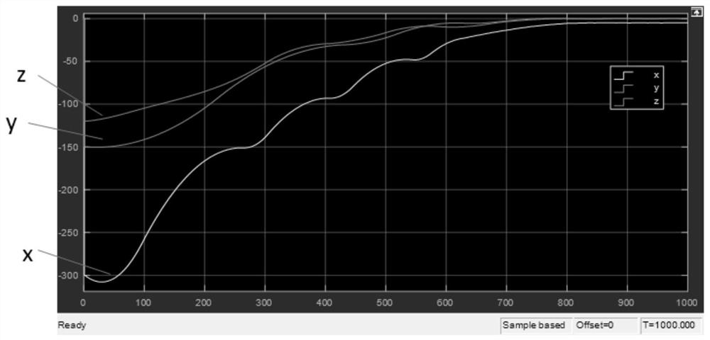
[0114] In the simulation, reduce the propulsion acceleration (reducing the thrust size or increasing star mass) and reduce the guidance control cycle can improve the guidance control accuracy, the control command is less affected by the intersection of the approximation control results, the simulation results are Figure 3 - Figure 7 Indicated. The above simulation results show that through a very simple thrust layout scheme, the perfect decoupling of the star and rotation can be guaranteed; and the phase-plane guidance control scheme can ensure smooth convergence of each channel of the three-way channel; Based on the thrust hybrid scheduling algorithm to ensure a flat control effect in the process of approximation of the spacecraft, create a good end docking condition. It can be seen that the product and method of the present invention can successfully solve the free control of the aerospactor in the case of the thrust device, and can achieve higher control accuracy.
[0115] Although the embodiments of the present invention are described above, it should be understood that they are only presented as an example, not limiting. Those skilled in the relevant art will apparent that various combinations, variations, and variations can be made without departing from the spirit and scope of the invention. Therefore, the width and range of the present invention disclosed herein should not be limited by the above-described exemplary embodiments, but will be defined only by the appended claims and their equivalents.

PUM

no PUM

Description & Claims & Application Information

We can also present the details of the Description, Claims and Application information to help users get a comprehensive understanding of the technical details of the patent, such as background art, summary of invention, brief description of drawings, description of embodiments, and other original content. On the other hand, users can also determine the specific scope of protection of the technology through the list of claims; as well as understand the changes in the life cycle of the technology with the presentation of the patent timeline. Login to view more.
Why Eureka
Try Eureka