A roller type automatic conveying machine

A conveying machinery and roller type technology, applied in the field of roller type automatic conveying machinery, can solve the problems of affecting the conveying effect, increasing the equipment investment cost of the manufacturer, and easy inclination of pipe fittings or rods, so as to avoid accidental rotation.

Active Publication Date: 2021-09-24
山东柏源技术有限公司
View PDF0 Cites 0 Cited by
  • Summary
  • Abstract
  • Description
  • Claims
  • Application Information

AI Technical Summary

Problems solved by technology

[0003] However, the following problems will occur during the working process of the roller-type automatic conveying equipment: 1. The conveying rollers in the traditional roller-type automatic conveying equipment are mostly cylindrical structures, and the structure is relatively simple, and the pipe fittings or rods with a linear structure When conveying, the conveying roller cannot limit it, resulting in the linear structure of pipes or rods prone to inclination during the conveying process, thus affecting the conveying effect
[0004] 2. The length of the conveying roller in the traditional roller-type automatic conveying equipment is mostly fixed, so when conveying large-volume materials, it is necessary to replace the corresponding conveying roller for conveying, and different volumes of materials need to use different conveying equipment , which increases the manufacturer's equipment input cost

Method used


Image

  • A roller type automatic conveying machine
  • A roller type automatic conveying machine
  • A roller type automatic conveying machine

Examples


Embodiment Construction

[0026] The embodiments of the present invention will be described in detail below with reference to the accompanying drawings, but the present invention can be implemented in many different ways defined and covered by the claims.

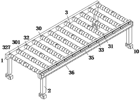
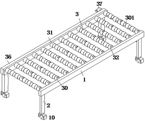
[0027] refer to figure 1 , a drum-type automatic conveying machine, including a support frame 1, a support leg 2 and a transmission mechanism 3, the support frame 1 is symmetrically arranged front and rear, and the support leg 2 is symmetrically installed on the lower end surface of the support frame 1, and the support frame 1 A transmission mechanism 3 is installed between them.

[0028] refer to figure 1 , the lower end surface of the support leg 2 is equipped with moving wheels 10, which facilitates the movement of the equipment.

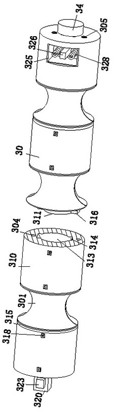
[0029] refer to figure 1 and Figure 4 , the transmission mechanism 3 includes a transmission drum 30, a first rotating shaft 33, a second rotating shaft 34, a chain 35, an end cover 36 and a motor 37, and the fron...


PUM


Abstract

The invention relates to the technical field of conveying equipment, in particular to a roller-type automatic conveying machine, which includes a support frame, support legs and a transmission mechanism. The support frame is symmetrically arranged front and back, and the support legs are symmetrically installed on the lower end surface of the support frame. A transmission mechanism is installed between the support frames. The transmission mechanism used in the present invention realizes the function of transporting large-volume objects by pushing the moving column into the placement groove. A concave groove is formed between the moving column and the sleeve to support square pipes or Square rods are transported, and the arc groove formed between the arc frame and the sleeve is convenient for transporting round pipes or round rods. It can transport a variety of materials and achieve the effect of one machine with multiple functions, avoiding the The pipe fittings or rods with linear structure have the problem of inclination during the conveying process. At the same time, the fixed roller and the movable roller in the conveying mechanism are detachably connected, and the length of the conveying roller can be adjusted to realize the conveying of materials of different volumes. Function.

Description

technical field [0001] The invention relates to the technical field of conveying equipment, in particular to a roller-type automatic conveying machine. Background technique [0002] Roller conveying is suitable for conveying all kinds of rods, pipe fittings, boxes, bags, pallets and other goods. It can convey a single piece of heavy material and withstand a large impact load. The rollers are easy to connect and filter, and multiple rollers can be used And other conveyors or special planes to form a complex logistics transportation system, which can meet various technological needs, and has the characteristics of large transportation volume, fast speed and brisk operation. [0003] However, the following problems will occur during the working process of the roller-type automatic conveying equipment: 1. The conveying rollers in the traditional roller-type automatic conveying equipment are mostly cylindrical structures, and the structure is relatively simple, and the pipe fitti...

Claims


Application Information

Patent Timeline
Patent Type & Authority Patents(China)
IPC IPC(8): B65G13/07B65G47/22B65G39/02B65G41/00B65G39/04
CPCB65G13/07B65G39/02B65G39/04B65G41/008B65G47/22B65G2201/0217B65G2201/0276
Inventor 黄聪
Owner 山东柏源技术有限公司
Why Eureka
Try Eureka