High-safety fuel cell electrolytic bath system and working method thereof

A fuel cell, high-safety technology, applied in the field of electrolysis cells, can solve problems such as hidden safety hazards, inconvenient use, and low efficiency of SOEC systems

Active Publication Date: 2021-08-20
北京思伟特新能源科技有限公司
View PDF16 Cites 6 Cited by
  • Summary
  • Abstract
  • Description
  • Claims
  • Application Information

AI Technical Summary

Problems solved by technology

[0004] This SOEC system has the following deficiencies: 1. The system needs at least two electric heaters, two heat exchangers, and a circulating pump, etc., and there are many components, which are large in size and inconvenient to use; 2. Hydrogen and water The mixed gas needs to be heated by electricity, which has potential safety hazards; 3. The utilization rate of water vapor is low, resulting in low efficiency of the entire SOEC system

Method used


Image

  • High-safety fuel cell electrolytic bath system and working method thereof
  • High-safety fuel cell electrolytic bath system and working method thereof
  • High-safety fuel cell electrolytic bath system and working method thereof

Examples


no. 1 Embodiment approach

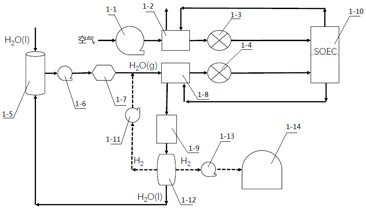
[0035]as attached figure 2 As shown, a high-safety fuel cell electrolyzer system includes: fan 1, air heat exchanger 2, electric heater 3, air-gas heat exchanger 4, water tank 5, water pump 6, steam generator 7, gas Heat exchanger 8, mixer 9, SOEC stack 10, condenser 11, water-gas separator 12, booster pump 13, high-pressure gas cylinder 14, flow meter 15.

[0036] The blower 1, the air heat exchanger 2, the electric heater 3, and the air-gas heat exchanger 4 are connected in sequence to form a supply flow path on the cathode side. The fan 1 is used to compress the air and send it to the air heat exchanger 2; the air heat exchanger 2 is used to send the air sent by the fan 1 and the high-temperature cathode tail gas discharged from the SOEC stack 10 heat exchange; the electric heater 3 is used to heat the air; the air-gas heat exchanger 4 is used to exchange heat between the high-temperature air heated by the electric heater 3 and the water vapor on the anode side. The abov...

no. 2 Embodiment approach

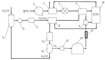
[0044] as attached image 3 As shown, a high-safety fuel cell electrolyzer system includes: fan 1, air heat exchanger 2, electric heater 3, air-gas heat exchanger 4, water tank 5, water pump 6, steam generator 7, gas Heat exchanger 8, mixer 9, SOEC stack 10, condenser 11, water-gas separator 12, booster pump 13, high-pressure gas cylinder 14, flow meter 15, high-temperature circulation pump 16.

[0045] The blower 1, the air heat exchanger 2, the electric heater 3, and the air-gas heat exchanger 4 are connected in sequence to form a supply flow path on the cathode side. The fan 1 is used to compress the air and send it to the air heat exchanger 2; the air heat exchanger 2 is used to send the air sent by the fan 1 and the high-temperature cathode tail gas discharged from the SOEC stack 10 heat exchange; the electric heater 3 is used to heat the air; the air-gas heat exchanger 4 is used to exchange heat between the high-temperature air heated by the electric heater 3 and the wa...

no. 3 Embodiment approach

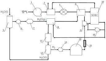
[0055] as attached Figure 4 As shown, a high-safety fuel cell electrolyzer system includes: fan 1, air heat exchanger 2, electric heater 3, air-gas heat exchanger 4, water tank 5, water pump 6, steam generator 7, gas Heat exchanger 8, ejector 17, SOEC stack 10, condenser 11, water-gas separator 12, booster pump 13, high-pressure gas cylinder 14, flow meter 15, valve 18.

[0056] The blower 1, the air heat exchanger 2, the electric heater 3, and the air-gas heat exchanger 4 are connected in sequence to form a supply flow path on the cathode side. The fan 1 is used to compress the air and send it to the air heat exchanger 2; the air heat exchanger 2 is used to send the air sent by the fan 1 and the high-temperature cathode tail gas discharged from the SOEC stack 10 heat exchange; the electric heater 3 is used to heat the air; the air-gas heat exchanger 4 is used to exchange heat between the high-temperature air heated by the electric heater 3 and the water vapor on the anode s...


PUM


Abstract

The invention provides a high-safety fuel cell electrolytic bath system and a working method thereof. The system comprises a fan, an air heat exchanger, an electric heater, an air-gas heat exchanger, a water tank, a water pump, a steam generator, a gas heat exchanger, a mixer and an SOEC stack. By arranging the air-gas heat exchanger, heat exchange is carried out on water vapor on the anode side and high-temperature air heated by the electric heater on the cathode side, the temperature of the water vapor is further increased, and high-temperature water vapor is formed. Compared with the prior art, a circulating pump and an anode electric heater are omitted, parts are reduced, and potential safety hazards are avoided. A high-temperature circulating pump or an ejector is adopted, water vapor in anode tail gas is recycled, the utilization rate of the water vapor is increased, and the efficiency of an SOEC system is improved.

Description

technical field [0001] The invention belongs to the technical field of electrolytic cells, and more specifically relates to a high-safety fuel cell electrolytic cell system and its working method. Background technique [0002] The solid oxide electrolytic cell (SOEC) is an advanced electrochemical energy conversion device, which can use the electricity and heat generated by clean primary energy to generate H 2 O and / or CO 2 It is expected to achieve large-scale energy efficient conversion and storage through efficient electrolysis to prepare hydrogen or hydrocarbon fuels as raw materials. [0003] Currently, most SOEC systems such as figure 1 As shown, on the cathode side, the air is compressed by the fan, and then enters the first electric heater through heat exchange with the high-temperature air coming out of the stack, and then enters the stack after heating the air to the set inlet temperature of the stack; on the anode side, the water pump from The water tank provid...

Claims


Application Information

Patent Timeline
Patent Type & Authority Applications(China)
IPC IPC(8): C25B1/042C25B1/50C25B9/00C25B9/67C25B15/08
CPCC25B1/04C25B9/00C25B15/08Y02E60/36
Inventor 刘亚迪胡浩然
Owner 北京思伟特新能源科技有限公司
Why Eureka
Try Eureka