Efficient energy-saving cold and heat supply station design system and method based on 3D/BIM foundation

A high-efficiency, energy-saving, system-design technology, applied in heating methods, air-conditioning systems, household heating, etc., can solve the problems of easy loss of thermal energy and affect the efficiency of thermal power plants, and achieve the effect of improving heating efficiency and reducing consumption

Active Publication Date: 2021-08-20
JIANGSU TUCHUANG SMART ENERGY CO LTD
View PDF5 Cites 3 Cited by
  • Summary
  • Abstract
  • Description
  • Claims
  • Application Information

AI Technical Summary

Problems solved by technology

[0004] The purpose of the present invention is to provide a 3D / BIM-based high-efficiency energy-saving cooling and heating energy station based on 3D / BIM, which can be heated by heat exchange treated water, can improve heating efficiency, can reduce heat energy consumption, and can keep hot water warm. Design a system and method to solve the problem in the above background technology that the thermal energy of the waste heat of circulating water is easily lost and affects the efficiency of thermal power plants

Method used


Image

  • Efficient energy-saving cold and heat supply station design system and method based on 3D/BIM foundation
  • Efficient energy-saving cold and heat supply station design system and method based on 3D/BIM foundation
  • Efficient energy-saving cold and heat supply station design system and method based on 3D/BIM foundation

Examples


Embodiment 1

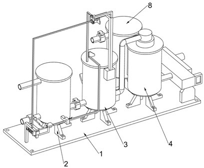
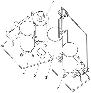
[0044] The design system and method of high-efficiency energy-saving cooling and heating station based on 3D / BIM, such as figure 1 , figure 2 , Figure 4 , Figure 5 and Figure 7 As shown, it includes a bottom plate 1, a transfer tank 2, a return pipe 201, a heating tank 3, a hot water storage tank 4, a data storage control unit 5, a heating unit 6, a hot water storage unit 7, a cold water storage unit 8 and a constant temperature unit 80. The top surface of the bottom plate 1 on the left side is connected to the transfer tank 2 by means of fasteners, the top of the transfer tank 2 is connected to the return pipe 201, and the top surface of the bottom plate 1 on the right side of the transfer tank 2 is connected by fasteners The heating tank 3 for storing residual hot water is connected by means of the heating tank 3, and the top surface of the bottom plate 1 on the right side of the heating tank 3 is connected with the hot water storage tank 4 for storing hot water by fa...

Embodiment 2

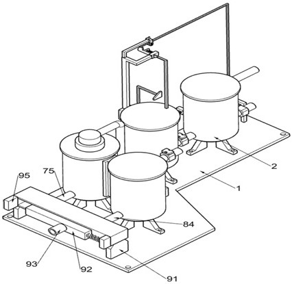
[0056] On the basis of Example 1, such as image 3 , Figure 8 and Figure 9 As shown, it also includes a liquid outlet adjustment unit 9, which is used to control the discharge of cold water and hot water. The right side of the bottom plate 1 is fixed with a liquid outlet adjustment unit 9, and the liquid outlet adjustment unit 9 includes The liquid guide frame 91, the movable liquid guide block 92, the drain pipe 93, the first tension spring 94 and the electromagnet 95, the liquid guide frame 91 is fixedly installed on the right side of the top surface of the bottom plate 1, and the liquid guide frame 91 is connected with the third conveying The right end of the tube 75 is connected, and the liquid guide frame 91 is also connected with the right end of the liquid outlet pipe 84. The liquid guide frame 91 is slidably connected with a movable liquid guide block 92, and the movable liquid guide block 92 is used to connect the third delivery pipe 75 or the liquid outlet pipe. ...

Embodiment 3

[0059] On the basis of Example 2, such as image 3 and 10 As shown, it also includes a floating adjustment part 10, the top of the heating tank 3 is slidably connected to the floating adjustment part 10, the floating adjustment part 10 includes a semi-circular floating plate 101 and an L-shaped push rod 102, and the top of the heating tank 3 is slidably connected to a The L-shaped push rod 102 is fixedly connected to the bottom end of the L-shaped push rod 102 with a semi-annular floating plate 101 , and the semi-annular floating plate 101 is located in the heating tank 3 .

[0060] Such as Figure 4 , Figure 11 and Figure 12 As shown, it also includes a limiting part 11, the heating tank 3 is provided with a limiting part 11, and the limiting part 11 includes a support block 111, a guide rod 112, a movable top plate 113, a second tension spring 114, a guide frame 115, a limiter Position bar 116 and limit spring 117, a support block 111 is fixedly installed above the hea...


PUM


Abstract

The invention relates to the field of efficient and energy-saving cold and heat supply station design systems, in particular to an efficient and energy-saving cold and heat supply station design system and method based on a 3D / BIM foundation. The system comprises a bottom plate, a transfer tank, a water return tube, a heating tank, a hot water storage tank and the like, wherein the transfer tank is connected to the left side of the top face of the bottom plate in a fastener connection mode, the heating tank is connected to the top face of the bottom plate in a fastener connection mode, and the heating tank is used for storing hot water; the top face of the bottom plate is connected with the hot water storage tank used for storing hot water in a fastening piece connecting mode, and the hot water storage tank is located on the right side of the heating tank. Water subjected to heat exchange treatment enters the transfer tank, a first electromagnetic valve opens a first conveying tube, the water in the transfer tank enters the heating tank, and a heating wire heats the water with waste heat in the heating tank, so that the water can be rapidly heated, the heating efficiency is improved, the consumption of heat energy is reduced, and the significance of energy conservation and emission reduction is achieved.

Description

technical field [0001] The invention relates to the field of high-efficiency and energy-saving cooling and heating station design systems, in particular to a high-efficiency and energy-saving cooling and heating station design system and method based on 3D / BIM. Background technique [0002] In recent years, people’s demand for building heating is increasing day by day, and building energy consumption is relatively high, which brings great pressure on energy security. If the past energy consumption pattern continues, energy consumption will become increasingly overwhelmed, and vigorously promote thermal power plant circulating water Waste heat utilization has great significance in energy saving and emission reduction. [0003] Existing cooling and heating systems usually take advantage of the river water’s “warm in winter and cool in summer” characteristics, and transport it to energy stations for heat energy conversion to provide users with green and stable cold and heat sou...

Claims


Application Information

Patent Timeline
Patent Type & Authority Applications(China)
IPC IPC(8): F24F5/00F24F11/89
CPCF24F5/0042F24F5/0046F24F11/89
Inventor 徐涛
Owner JIANGSU TUCHUANG SMART ENERGY CO LTD
Why Eureka
Try Eureka