Transmitting antenna for improving degree of freedom and distance in magnetic resonance wireless power transmission

A wireless power transmission and transmitting antenna technology, applied in transportation and packaging, current collectors, electric vehicles, etc., can solve the problems of large changes in the input impedance of the transmitting antenna, large difference in the transmission efficiency of the transmitting and receiving antennas, and poor horizontal degrees of freedom.

Pending Publication Date: 2021-08-20
CHENGDU SPROUTING TECH CO LTD
View PDF0 Cites 2 Cited by
  • Summary
  • Abstract
  • Description
  • Claims
  • Application Information

AI Technical Summary

Problems solved by technology

[0004] The purpose of the present invention is to solve the problem that the horizontal degree of freedom of wireless energy transmission in the market is poor when the transceiver antennas are parallel, the transmission efficiency of the transceiver antennas at different positions is quite different when the transceiver antennas are at a certain angle, and the receiving antennas are in different positions or different The input impedance of the transmitting antenna changes greatly when the distance is large, and a transmitting antenna for magnetic resonance wireless power transmission to improve the degree of freedom and distance is proposed

Method used


Image

  • Transmitting antenna for improving degree of freedom and distance in magnetic resonance wireless power transmission
  • Transmitting antenna for improving degree of freedom and distance in magnetic resonance wireless power transmission
  • Transmitting antenna for improving degree of freedom and distance in magnetic resonance wireless power transmission

Examples


Embodiment Construction

[0040] Embodiments of the present invention will be further described below in conjunction with the accompanying drawings.

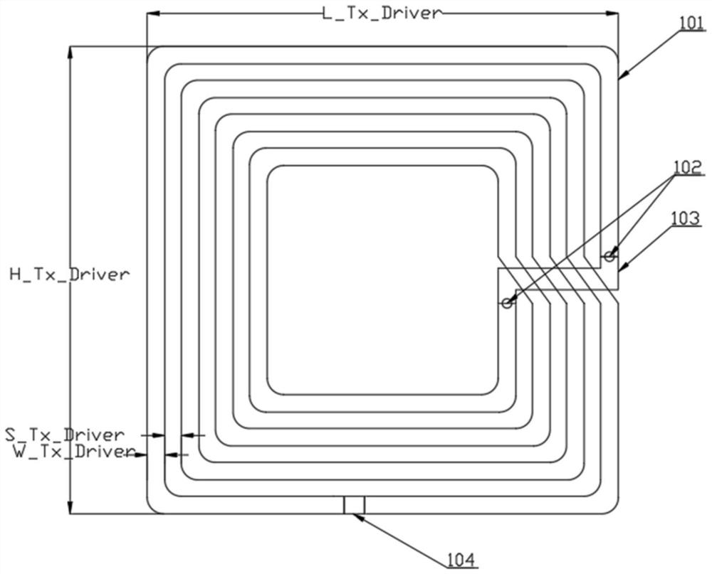
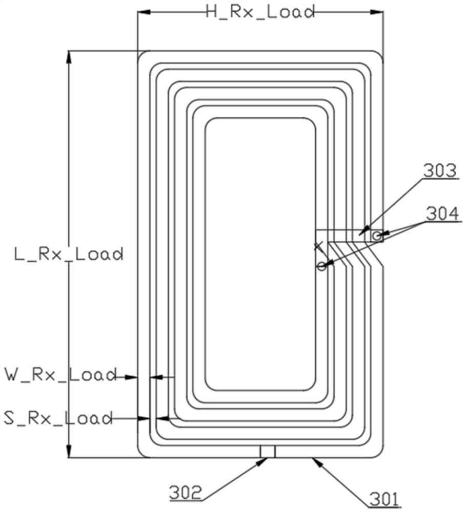
[0041] Such as figure 1 As shown, the present invention provides a transmitting antenna for magnetic resonance wireless power transmission to improve the degree of freedom and distance, including a transmitting antenna for magnetic resonance wireless power transmission and a receiving antenna for wireless power reception;

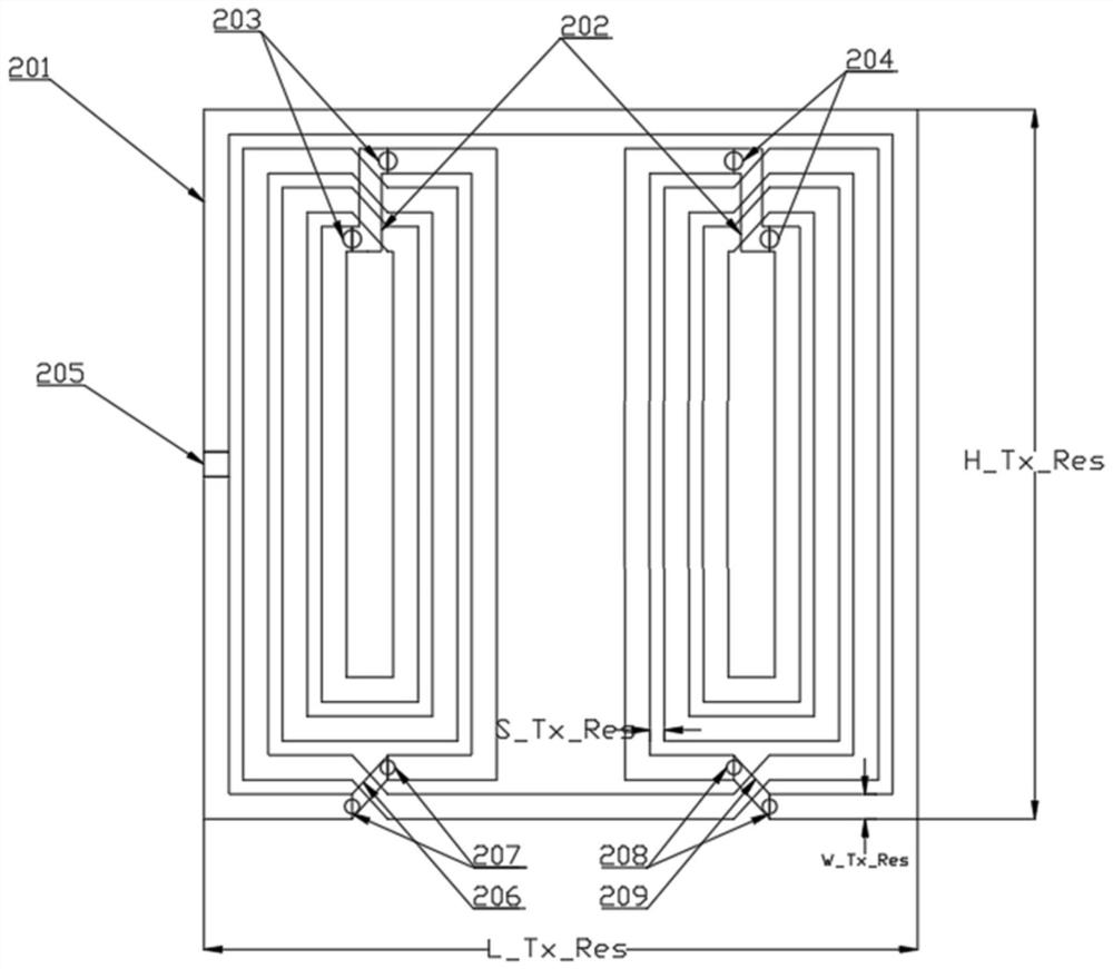
[0042] The transmitting antenna is an exciting resonant structure, including an exciting coil and a transmitting resonant coil; the exciting coil is a planar multi-turn coil; the transmitting resonant coil is composed of two planar multi-turn coils connected in series; the exciting coil is used to feed electromagnetic energy, and the electromagnetic The energy is coupled to the transmit resonant coil, which couples the electromagnetic energy magnetically to the receive coil. The two multi-turn coils in the transmitting resonant coil ...


PUM


Abstract

The invention discloses a transmitting antenna for improving the degree of freedom and distance in magnetic resonance wireless power transmission. The transmitting antenna comprises an exciting coil and a transmitting resonance coil, the exciting coil is a planar multi-turn coil; the transmitting resonance coil is formed by connecting two planar multi-turn coils in series; and the exciting coil is used for feeding in electromagnetic energy and coupling the electromagnetic energy to the transmitting resonance coil, and the transmitting resonance coil couples the electromagnetic energy to the receiving coil through magnetic resonance. The transmission efficiency of the transmitting antenna is kept stable at different charging distances and high-distance inclination angles; and the transmitting antenna is of a broadband matching structure, when receiving is carried out at different positions in a transmitting antenna field, the input impedance change of the transmitting antenna is very small, and matching between the output impedance of the power amplifier and the input impedance of the transmitting antenna is ensured.

Description

technical field [0001] The invention belongs to the technical field of wireless power transmission, and in particular relates to a transmitting antenna for improving the degree of freedom and distance of magnetic resonance wireless power transmission. Background technique [0002] With the continuous development of electronic information technology and automation control technology, various home appliances, consumer electronics, mobile communication equipment, etc. have been widely popularized. However, traditional household appliances rely Electronic devices with built-in batteries also need a wired connection between the charging cable and the power outlet for charging, so we can see wires that provide power supply for these electronic devices everywhere. These wires not only occupy our activity space, limit the convenience of equipment use, but also create hidden dangers for safe use of electricity. Therefore, with the growing demand for portable devices and green energy...

Claims


Application Information

Patent Timeline
Patent Type & Authority Applications(China)
IPC IPC(8): H02J50/23H02J50/12H02J7/00H01Q1/38
CPCH01Q1/38H02J7/00H02J50/12H02J50/23
Inventor 喻易强李伟罗鑫刘勇
Owner CHENGDU SPROUTING TECH CO LTD
Why Eureka
Try Eureka