
Device for driving a shaft of a jet engine for inspection purposes

A technology of jet engines and equipment, applied in mechanical equipment, engine functions, engine components, etc.

Pending Publication Date: 2021-08-20
LUFTHANSA TECH AG
View PDF8 Cites 0 Cited by
  • Summary
  • Abstract
  • Description
  • Claims
  • Application Information

AI Technical Summary

Problems solved by technology

The downside here is that two workers are required to inspect the mentioned turbine blades

Method used


Image

  • Device for driving a shaft of a jet engine for inspection purposes
  • Device for driving a shaft of a jet engine for inspection purposes
  • Device for driving a shaft of a jet engine for inspection purposes

Examples


Embodiment Construction

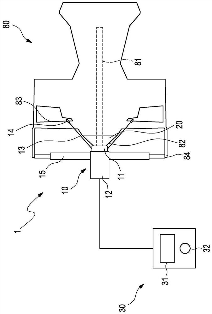
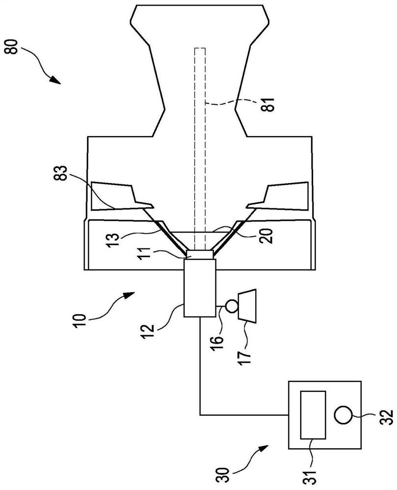
[0041] exist figure 1 In , a first embodiment of the device 1 of the invention is shown.

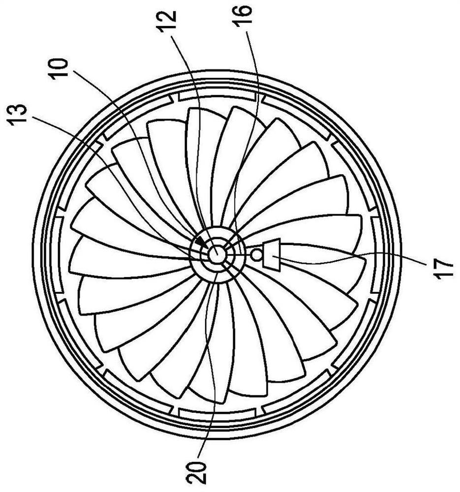
[0042] The device 1 is designed to drive a shaft 81 of a jet engine 80 , the rotor 82 of which is the visible so-called nose cone of the jet engine 80 from the outside, on which fan blades 83 are fastened in a rotationally fixed manner.

[0043] The device 1 comprises a drive unit 10 having two parts 11 , 12 rotatable relative to each other, one part 11 co-rotating with the shaft 81 of the jet engine 80 and the other part 12 not co-rotating therewith.

[0044] The co-rotating part 11 is designed to bear against the rotating part 82 of the shaft 81 and for this purpose has a negatively shaped contact surface matching the shape of the rotating part 82 . In order to increase the adhesion between this contact surface and the rotating part 82, between the co-rotating part 11 of the drive unit 10 and the rotating part 82 there is provided an adhesion-improving element 20 made of an elastomer ...


PUM


Abstract

The invention relates to a device (1) for driving a shaft (81) of a jet engine (80) for inspection purposes. In one embodiment, the device (1) comprises a drive unit (10) having a part (11) co-rotating with the shaft, wherein the co-rotating part (11) of the drive unit (10) is designed to lie against the spinner (82) of the shaft (81) and is rotationally fixed to one or more fan blades (83) arranged on the shaft (81) by at least one strap (13) In another embodiment, the device (1) comprises a drive unit (10) having a clamping element for detachable and non-destructive securing of the drive unit (10) to a fan blade (83) of the jet engine (80) arranged on the shaft (81), and having a friction wheel (19) driven by the drive unit (10) and designed to lie against the housing (84) of the jet engine (80).

Description

technical field [0001] The invention relates to a device for driving the shaft of a jet engine for inspection purposes. Background technique [0002] Aircraft jet engines must be inspected regularly to check compliance with technical safety requirements and to detect possible damage early. In particular, when a jet engine is mounted on an aircraft (on the wing) for inspection, side valves to the jet engine are opened and / or individual components are removed to allow the technician to view the interior of the jet engine either directly or with the aid of a borescope . [0003] In order to inspect the rotatable part of the jet engine, it is also known that the jet engine is guided through the viewing opening of the jet engine or inserted at the bore sight of the jet engine, so that the entire circumference of the rotatable part of the jet engine is passed in sequence Opening or bore peeper's field of view. Of course, it is also possible to move the rotatable part of the jet...

Claims


Application Information

Patent Timeline
Patent Type & Authority Applications(China)
IPC IPC(8): F01D25/28B64F5/40B64F5/60F01D25/36
CPCF05D2220/36F01D25/36F05D2260/402F01D25/285B64F5/60F02C7/32F05D2260/80
Inventor 杨·奥克·彼得斯迈克尔·蒂斯约翰·波特
Owner LUFTHANSA TECH AG
Learn More