
Compositions and methods for evaluation of liquid contact angle properties

a liquid contact angle and composition method technology, applied in the field of features evaluation, can solve the problems of time-consuming and laborious, large-scale real-time use, and excessive complexity of the analysis of microscopic features on the surface of an obj

Pending Publication Date: 2022-04-21
TEXAS A&M UNIVERSITY
View PDF4 Cites 0 Cited by
  • Summary
  • Abstract
  • Description
  • Claims
  • Application Information

AI Technical Summary

Benefits of technology

The present patent provides new methods for evaluating objects such as liquid droplets and surfaces. These methods can identify small defects without the need for a complicated system. They can improve surface coating efficiency and production time. The methods can be applied regardless of the sample's transparency and can measure the thin height and low contact angle of micro droplets. The described methods can effectively measure the droplet height and contact angle from 1 micron to 16 microns. This allows for the detection of small droplets and surfaces.

Problems solved by technology

The analysis of microscopic features on the surface of an object is exceedingly complex.
Current systems are only capable of scanning a very small area, thus preventing real-time usage for large areas.
Moreover, currently available techniques in real-production line rely on time consuming methods such as steam-condensation generation, which monitors droplet formation on the surface by trying to observe abnormal droplet formation caused by surface defect.
This method requires considerable time for the steam droplet to evaporate and can result in undesirable surface stain.
Moreover, the characterization of fingerprints with real human sebum is challenging because of its complicated shape and because the real human sebum contains various kinds of liquids and solid particles like a turbid medium, causing difficulty in obtaining consistent measurements.
Current methods in the art to measure this small thickness are only possible through the counting the number of the fringes in interference using the sophisticated microscope.

Method used


Image

  • Compositions and methods for evaluation of liquid contact angle properties
  • Compositions and methods for evaluation of liquid contact angle properties
  • Compositions and methods for evaluation of liquid contact angle properties

Examples


example 1

[0063]Dual Profile of Droplet Surface

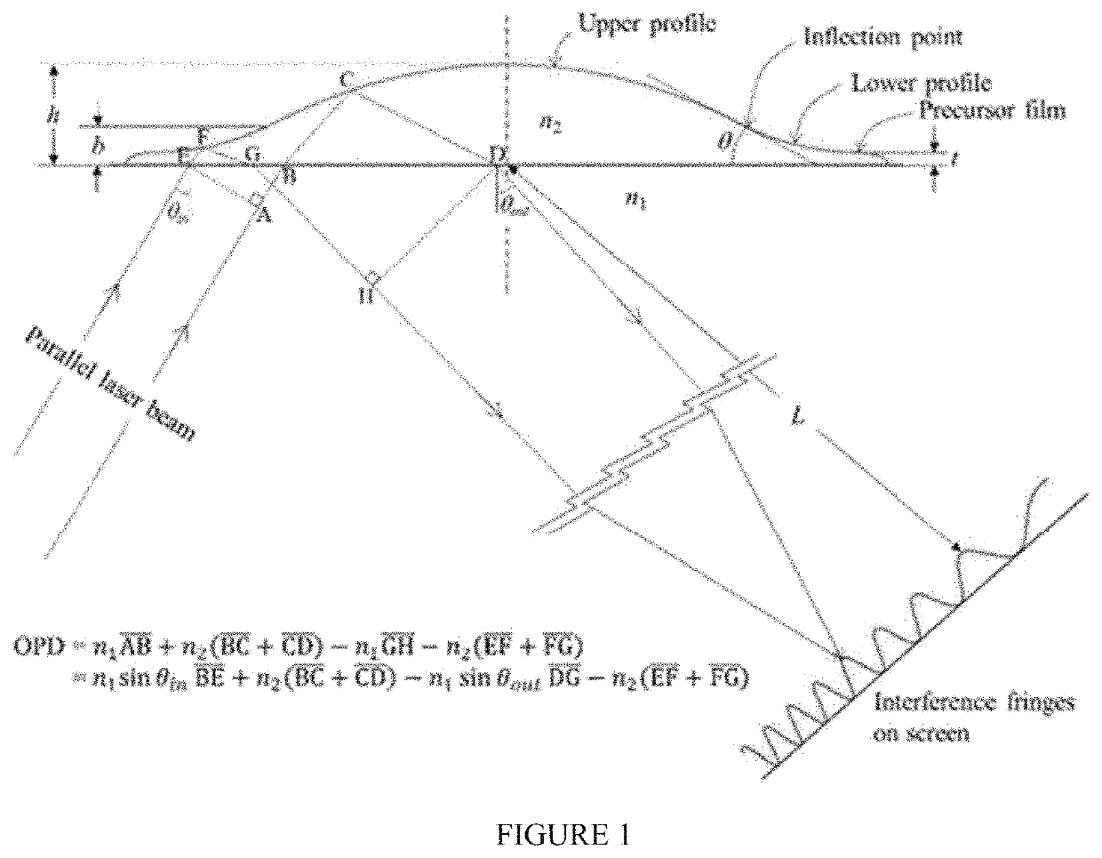
[0064]A sessile droplet is formed with two parts in its surface profile. One part is an upper profile that is a macroscopic dorm placing on the apex of droplet. The second part is a lower profile that is mesoscopic film attached at the contact line of droplet. Both profiles are connected along an inflection line (FIG. 1). The dual droplet profile is defined with several parameters such as the droplet's height (h), the droplet's radius (r), the radial (a) and the axial (b) coordinates of inflection line, and the thickness of precursor film.

[0065]In the instant example the upper profile shape is presumed to be a spherical cap and the lower profile shape is presumed to be a hyperbola curve. The contact angle of droplet is defined as the slope of droplet surface at the inflection point. The profile of spherical cap can be obtained with droplet height, the coordinates of inflection point, and a contact angle that is associated with the curvature of sp...

example 2

Internal Reflection and Interference Fringes

[0068]The interference fringe is made by the internal reflection (IR) system with an equilateral triangle prism (SF10, n=1.732 at 633 nm). The optical ray tracing about total internal reflection on a droplet surface is illustrated in FIG. 1. A droplet is placed on the upper side of prism. A He—Ne laser (λ=633 nm) is used as a light source to produce the interferometric fringes of light on a screen. A coherent, parallel beam (w=0.8 mm) of a laser is incident on the left side of prism and reflects on the upper surface of liquid droplet. Total internal reflection associated with a liquid droplet involves the optical aberration of reflection beam due to the curved profile of droplet surface. The laser beam reflected on the droplet surface is not parallel any more while it passes out through the right side of prism. Eventually, due to the dual profile of droplet surface, the laser beam arrives at different coordinates on a screen according to t...

example 3

Optical Path Difference

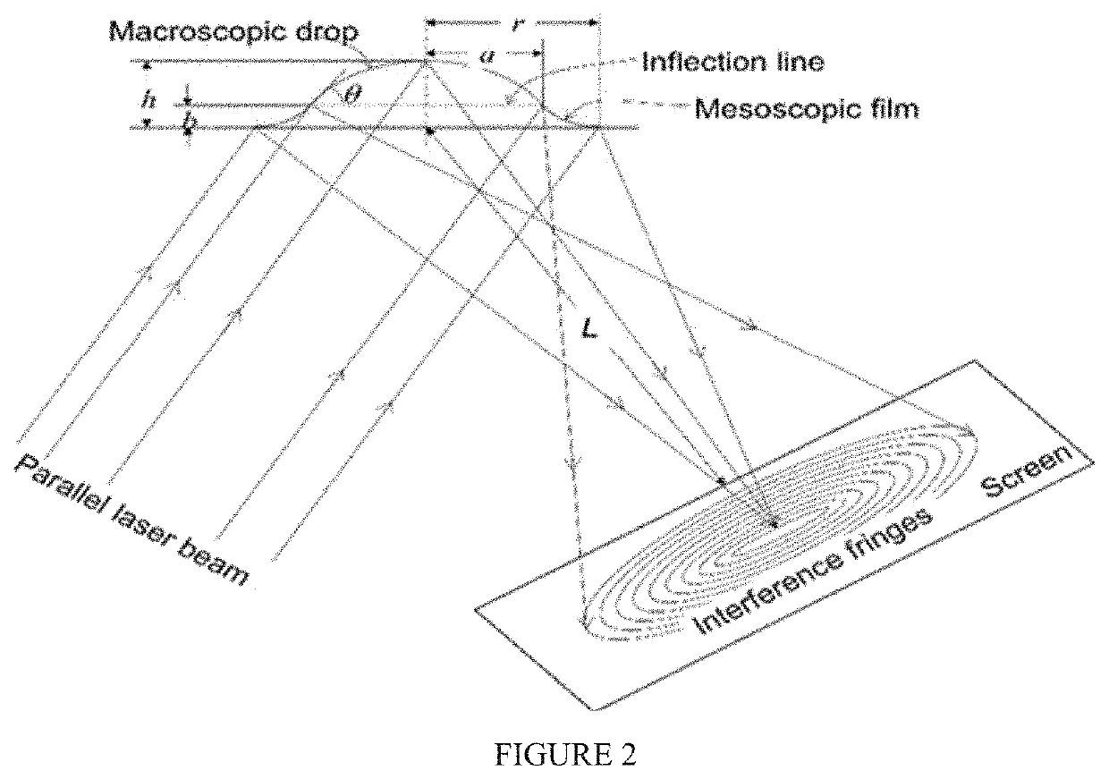
[0070]Calculating the optical path difference is determined by how the interference fringes are formed on the screen. Two parallel rays are reflected on the dual profile of the droplet and projected to the same point on the screen, which is far away from the droplet (L) (FIG. 2). The optical path difference (OPD) between the two beams can be seen as the distance difference between line ABCD and line EFGH. The recursive OPD formula is obtained by multiplying the physical distance by the refractive index of the medium.

OPD=n1⁢AB_+n2⁡(BC_+CD_)-n1⁢GH_-n2⁡(EF_+FG_)=n1⁢sin⁢⁢θin⁢BE_+n2⁡(BC_+CD_)-n1⁢sin⁢⁢θout⁢DG_-n2⁡(EF_+FG_)

[0071]The interference patterns appearing on the screen are related to the OPD obtained in the previous step. If the OPD is an integral multiple of the wavelength of the laser beam used, constructive interference occurs to create a bright pattern. There is a dark area between the two bright patterns, which occurs when the OPD is an integer multiple...


PUM


Abstract

The present disclosure relates to methods for evaluating features of objects such as liquid droplets and surfaces. More particularly, the present disclosure relates to methods for measuring features such as the contact angle and the thickness of an object such as a liquid droplet or a fingerprint as well as related compositions for evaluation.

Description

CROSS-REFERENCE TO RELATED APPLICATIONS[0001]This application claims the benefit under 35 USC § 119(e) of U.S. Provisional Application Ser. No. 63 / 092,604, filed on Oct. 16, 2020, the entire disclosure of which is incorporated herein by referenceBACKGROUND AND SUMMARY[0002]The present disclosure relates to methods for evaluating features of objects such as liquid droplets and surfaces. More particularly, the present disclosure relates to methods for measuring features such as the contact angle and the thickness of an object such as a liquid droplet or a fingerprint as well as related compositions for evaluation.[0003]The analysis of microscopic features on the surface of an object is exceedingly complex. For instance, a sophisticated microscope system must currently be utilized to evaluate contact angles of droplets and small defects on a surface. Current systems are only capable of scanning a very small area, thus preventing real-time usage for large areas. Moreover, currently avai...

Claims


Application Information

Patent Timeline
IPC IPC(8): G01N21/552G01B11/06G01N21/958
CPCG01N21/552G01N2021/555G01N21/958G01B11/06G01N2013/0208G01B11/26G01N13/02G01N21/94G01N2021/945G01N2021/8427
Inventor KIM, ILTAI ISAACLIE, YANGPARK, JAE SUNG
Owner TEXAS A&M UNIVERSITY
Learn More