
Induction femoral artery compression hemostat

A technology of compressing hemostasis and femoral artery, which is applied in the field of hemostats, can solve the problems of restricting the patient's activity space and cumbersome operations, and achieve the effects of reducing costs, simplifying operation steps, and avoiding cross-infection

Pending Publication Date: 2021-08-24
无锡东峰怡和科技发展有限公司
View PDF5 Cites 0 Cited by
  • Summary
  • Abstract
  • Description
  • Claims
  • Application Information

AI Technical Summary

Problems solved by technology

Although the above three femoral artery compression hemostats are easy to operate and have high safety, they are cumbersome to operate when adjusting the wound pressure and limit the patient's activity space

Method used


Image

  • Induction femoral artery compression hemostat
  • Induction femoral artery compression hemostat
  • Induction femoral artery compression hemostat

Examples


Embodiment 1

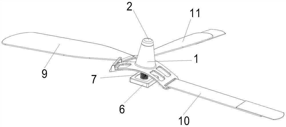
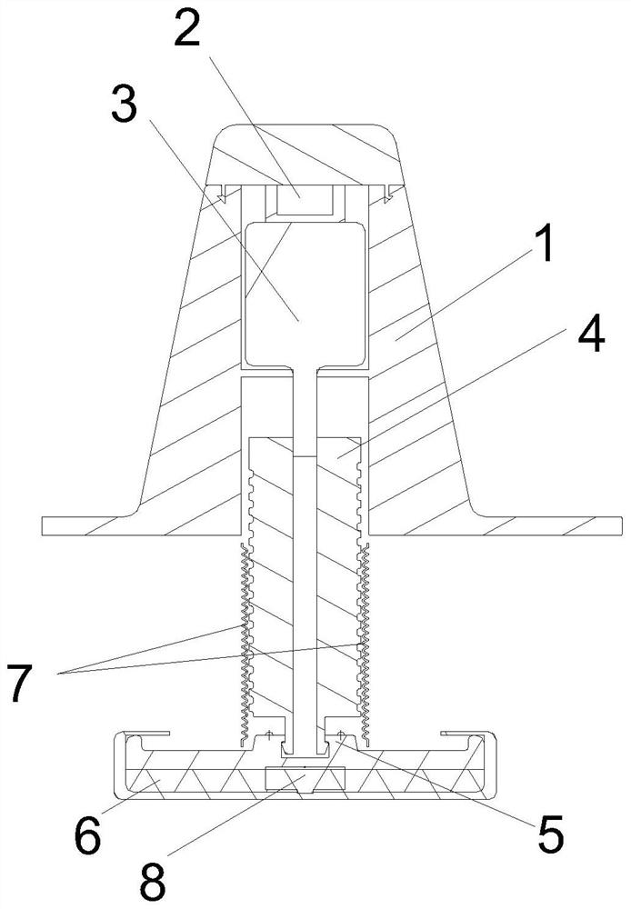
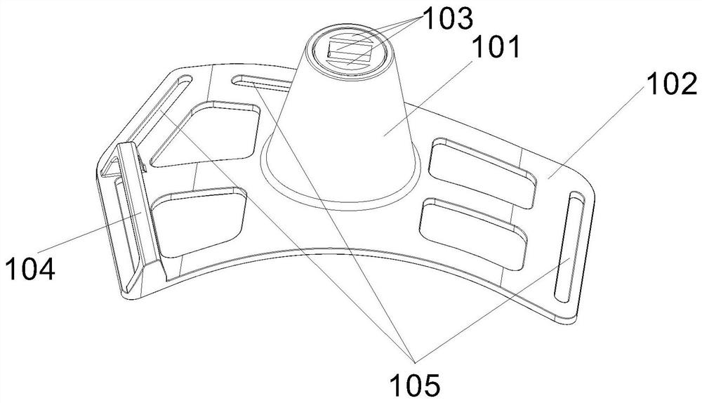
[0029] Such as Figure 1 to Figure 4 As shown, a sensing femoral artery compression hemostat includes an adjustment device 1, a battery compartment cover 2, a motor 3, an adjustment column 4, a flexible backing plate 6 and several straps; the straps are hung on the adjustment device 1. The battery compartment cover 2 is connected to the upper end of the adjustment device 1, the motor 3 is arranged inside the adjustment device 1 and is nested and connected with the adjustment column 4; the adjustment column 4 is covered with a telescopic sleeve 7. The flexible backing plate 6 is arranged at the lower end of the adjustment device 1, and a support block 5 is arranged on it, and the support block 5 is connected and fixed with the adjustment column 4, and a pressure sensor 8 is arranged therein.

[0030] In a further step of this embodiment, the adjustment device 1 includes an integrally formed adjustment plate and a bent plate 101, a barb is provided at the lower end of the batter...

Embodiment 2

[0040] Such as Figure 1 to Figure 4 Shown, a kind of operation method of induction femoral artery compression hemostat comprises the following specific steps:

[0041] S1: Check the tightness of the paper-plastic bag, unpack it after confirming the seal, and check whether the hemostat is intact;

[0042] S2: The operator and the assistant put on clean medical gloves and assemble: connect the battery compartment cover 2 to the upper end of the adjustment device 1;

[0043] S3: Set the pressure adjustment threshold: adjust the adjustment device 1 up and down along the adjustment column 4 to control the pressure of the hemostat on the patient's wound;

[0044] S4: Hold the handle 104 on the adjusting device 1, align the flexible backing plate 6 with the patient's wound, arrange the bandages and tie them on the patient in turn for fixing.

[0045] The operation method of the present invention is simple and fast, so that the pressure on the wound can be adjusted efficiently duri...


PUM


Abstract

The invention discloses an induction femoral artery compression hemostat. The hemostat comprises an adjusting device, a battery bin cover, a motor, an adjusting column, a flexible base plate and a plurality of bandages. The bandages are hung on the adjusting device, the battery bin cover is connected to the upper end of the adjusting device, and the motor is arranged in the adjusting device and connected with the adjusting column in a nested mode; and the adjusting column is sleeved with a telescopic sleeve. The flexible base plate is arranged at the lower end of the adjusting device, a supporting block is arranged on the flexible base plate, the supporting block is fixedly connected with the adjusting column, and a pressure sensor is arranged in the supporting block. Compared with the prior art, the induction femoral artery compression hemostat has the advantages that the length and the diameter of the puncture outfit can be adjusted at will through the adjusting device of the rhombic structure, operation steps of a doctor are greatly simplified, and the equipment selection time and the operation time are shortened; the sleeve assembly is made of plastic materials, and it is guaranteed that the wave structure at the lower end has certain elasticity. The puncture effect is good, and an operation channel can be accurately and firmly established.

Description

Technical field: [0001] The invention relates to a hemostat, in particular to a hemostat inductive to femoral artery compression. Background technique: [0002] Background: The predecessor of femoral artery compression hemostat is sandbag compression. Sandbag compression method: After the interventional operation is completed, the operator first manually presses the patient's femoral artery puncture site for 10 to 15 minutes. Then use about 0.5kg of sandbags to press the continuous puncture site for more than 6 hours, and brake the punctured limb for 24 hours. Due to the manual + sandbag compression method, there are disadvantages such as difficult control of compression, time-consuming and labor-intensive work for doctors, strong discomfort for patients, and long braking time. A femoral artery compression hemostat was invented to reduce the burden on doctors and reduce the pain of patients. The femoral artery compression hemostat has the advantages of simple operation, h...

Claims


Application Information

Patent Timeline
IPC IPC(8): A61B17/12
CPCA61B17/12A61B2017/12004
Inventor 钱海艳钱海军张淼张涛
Owner 无锡东峰怡和科技发展有限公司
Learn More