Electromagnetic spraying device and using method thereof
A spraying device and electromagnetic technology, applied in the direction of spraying device, spraying device, liquid spraying device, etc., can solve the problems of high environmental pollution, waste of paint particles, complicated spraying equipment, etc., to avoid environmental pollution, ensure uniformity, and improve spraying efficiency effect
- Summary
- Abstract
- Description
- Claims
- Application Information
AI Technical Summary
Problems solved by technology
Method used
Image


Examples
Embodiment approach
[0044] The invention provides an electromagnetic spraying device, which includes an inert gas source and an electromagnetic spraying mechanism. The outlet end of the inert gas source is connected to the air inlet of the electromagnetic spraying mechanism. The electromagnetic spraying mechanism includes a solenoid valve 1, a paint tank 2, several stages of electromagnetic Acceleration mechanism, main control center 6, nozzle 7, acceleration pipeline 8, coil controller 9, ring support 10, diffuser mechanism 12 and paint chamber 13.
[0045] The paint tank 2 is used to store the paint to be sprayed, and the discharge port of the paint tank 12 is connected with the feed port of the paint chamber 13; The outlet port of the paint chamber 1 is connected; the solenoid valve 1 is arranged at the air inlet of the paint chamber 13, and the solenoid valve 1 is set at the air inlet of the paint chamber 13, so that the flow rate of the inert gas into the paint chamber 13 can be controlled by...
Embodiment
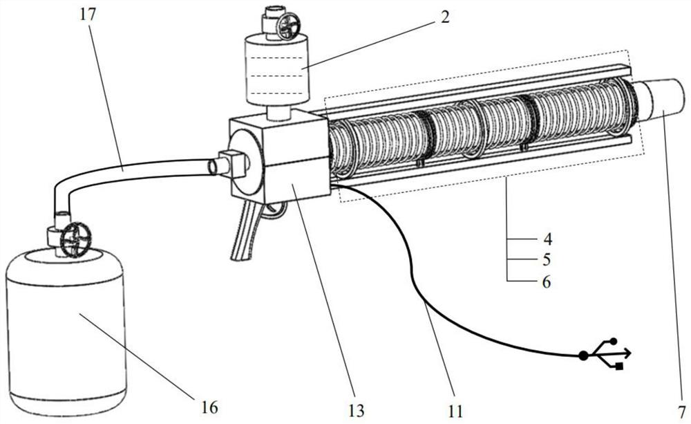
[0055] as attached Figure 1-7 As shown, this embodiment provides an electromagnetic spraying device, including a solenoid valve 1, a paint tank 2, a first-stage electromagnetic acceleration mechanism 3, a second-stage electromagnetic acceleration mechanism 4, a third-stage electromagnetic acceleration mechanism 5, and a main control center 6. Nozzle 7, acceleration pipeline 8, coil controller 9, ring bracket 10, power cord 11, diffuser mechanism 12, paint chamber 13, switch 14, handle 15, inert gas tank 16 and intake hose 17.
[0056] The solenoid valve 1 and the coil controller 9 are respectively connected to the main control center 6 by communication, and the first-stage electromagnetic acceleration mechanism 3, the second-stage electromagnetic acceleration mechanism 4 and the third-stage electromagnetic acceleration mechanism 5 are respectively connected to the coil controller 9 by communication; Gas tank 16 is used for storing inert gas, and inert gas tank 16 is connected...
PUM
 Abstract
Description
Claims
Application Information
 - R&D
- Intellectual Property
- Life Sciences
- Materials
- Tech Scout
- Unparalleled Data Quality
- Higher Quality Content
- 60% Fewer Hallucinations
Browse by: Latest US Patents, China's latest patents, Technical Efficacy Thesaurus, Application Domain, Technology Topic, Popular Technical Reports.
© 2025 PatSnap. All rights reserved.Legal|Privacy policy|Modern Slavery Act Transparency Statement|Sitemap|About US| Contact US: help@patsnap.com