Imaging lens
An imaging lens and lens technology, applied in the optical field, can solve problems such as poor lens performance, and achieve the effects of improving service performance, saving bonding, and saving installation steps
- Summary
- Abstract
- Description
- Claims
- Application Information
AI Technical Summary
Problems solved by technology
Method used
Image
Examples
Embodiment approach
[0067] According to one embodiment of the present invention, the connecting boss 213 is an annular boss (see Figure 5 ) or multiple arc-shaped bosses set at intervals (see Figure 6 ).
[0068] Such as Figure 7 As shown, according to an embodiment of the present invention, the axial height h of the connecting boss 213 satisfies: 0.08mm≤h≤1.5mm; the radial width d of the connecting boss 213 satisfies: d≥0.08mm.
[0069] Through the above arrangement, while ensuring the assembly accuracy of the present invention, the high-quality imaging of the present invention is also effectively guaranteed.
[0070] According to an embodiment of the present invention, the connecting boss 213 is formed by a plurality of arc-shaped bosses arranged at equal intervals, and there are at least three arc-shaped bosses. see Figure 6 As shown, in this embodiment, there are four arc-shaped bosses, and the four arc-shaped bosses are respectively arranged in a region whose central angle is 90°. O...
Embodiment 1
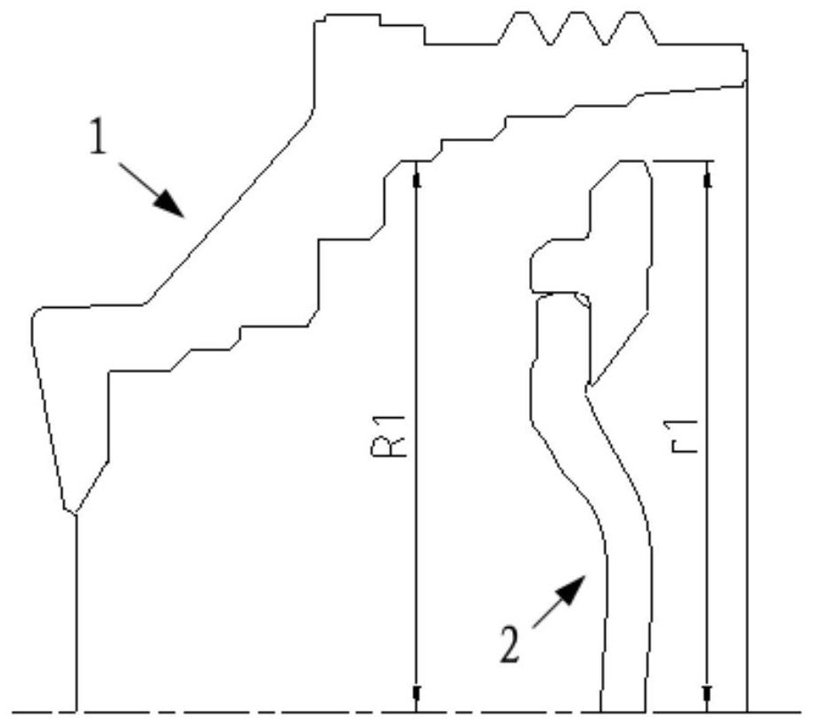
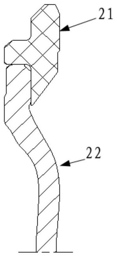
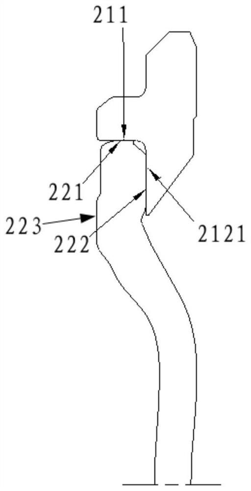
[0094] Such as Figure 15 As shown, in this embodiment, the imaging lens of the present invention includes a lens barrel 1 , a lens assembly 2 disposed in the lens barrel 1 , and a plurality of independent lenses. In this embodiment, the supporting spacer 21 in the lens assembly 2 is made of plastic material. The connecting boss 213 provided on the supporting spacer 21 is a straight boss (that is, the first spacer matching surface 211 and the second spacer matching surface 214 of the connecting boss in the radial direction are both cylindrical surfaces).
[0095] In this embodiment, a spacer is provided between the auxiliary bearing surface 13 of the lens barrel 1 and the lens assembly 2, and the convex surface 2131 of the connecting boss 213 abuts against the spacer, while the third lens mating surface of the lens 22 223 abuts against the spacer. Independent lenses are arranged at the front and back of the lens assembly 2 in the lens barrel 1 , thereby constituting the imag...
Embodiment 2
[0097] Such as Figure 16 As shown, in this embodiment, the imaging lens of the present invention includes a lens barrel 1 , a lens assembly 2 disposed in the lens barrel 1 , and a plurality of independent lenses. In this embodiment, the supporting spacer 21 in the lens assembly 2 is made of plastic material. The connecting boss 213 provided on the supporting spacer 21 is an oblique boss (that is, the first spacer matching surface 211 of the connecting boss in the radial direction is a cylindrical surface, and the second spacer matching surface 214 is a conical surface).
[0098] In this embodiment, a spacer is provided between the auxiliary bearing surface 13 of the lens barrel 1 and the lens assembly 2, and the convex surface 2131 of the connecting boss 213 is not in contact with the spacer, while the third lens mating surface of the lens 22 223 abuts against the spacer. Independent lenses are arranged at the front and back of the lens assembly 2 in the lens barrel 1 , the...
PUM
 Abstract
Description
Claims
Application Information
 - R&D
- Intellectual Property
- Life Sciences
- Materials
- Tech Scout
- Unparalleled Data Quality
- Higher Quality Content
- 60% Fewer Hallucinations
Browse by: Latest US Patents, China's latest patents, Technical Efficacy Thesaurus, Application Domain, Technology Topic, Popular Technical Reports.
© 2025 PatSnap. All rights reserved.Legal|Privacy policy|Modern Slavery Act Transparency Statement|Sitemap|About US| Contact US: help@patsnap.com


