Ultralow-temperature collimator device in vacuum environment

A collimating light tube, vacuum environment technology, applied in the measurement device, installation, optics and other directions, can solve the problems of lens and structural deformation, product functional damage, different structural parts materials, etc., to achieve small pressure loss, ensure overall accuracy, The effect of high heat exchange efficiency

Inactive Publication Date: 2021-08-24
SANHE LANSTECH OPTOELECTRONICS SCI & TECH CO LTD
View PDF9 Cites 0 Cited by
  • Summary
  • Abstract
  • Description
  • Claims
  • Application Information

AI Technical Summary

Problems solved by technology

[0005] The prior art discloses a photoelectric integrated collimator. In the actual application process, there are the aforementioned technical problems. When the temperature drops to -160°C, the lens and structure will be deformed, and the coating l

Method used


Image

  • Ultralow-temperature collimator device in vacuum environment
  • Ultralow-temperature collimator device in vacuum environment
  • Ultralow-temperature collimator device in vacuum environment

Examples


Embodiment

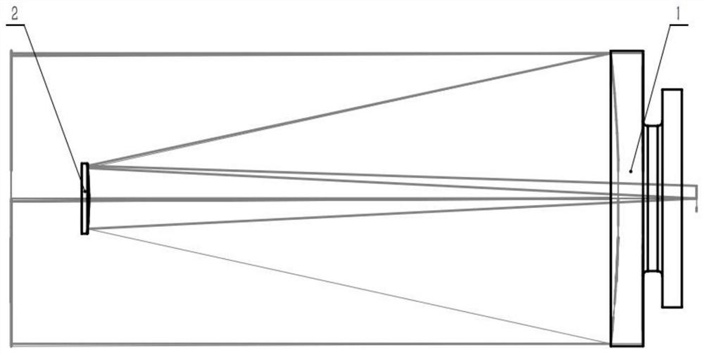
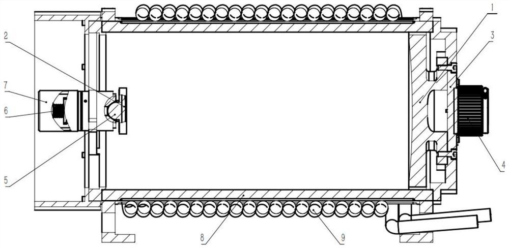
[0047] Such as Figure 1-2 As shown, the ultra-low temperature collimator device under the vacuum environment includes:

[0048] Support cylinder device 8;

[0049] The first reflector 1 is arranged at the right end of the support tube device 8;

[0050] The second reflector 2 is arranged at the left end of the support tube device 8, wherein the reflective surface of the first reflector 1 is opposite to the reflective surface of the second reflector 2;

[0051] The cooling device 9 is enclosed on the outside of the supporting cylinder device 8 .

[0052] In the above embodiments, the vacuum environment refers to a vacuum environment with an air pressure of 0 Pa;

[0053] The ultra-low temperature refers to the ambient air temperature ≤ -160°C;

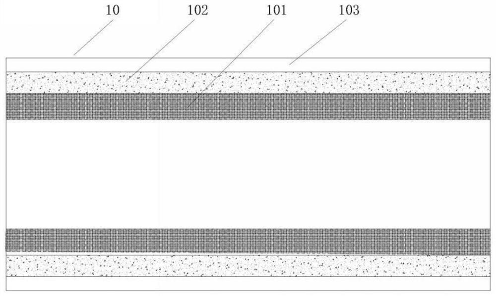
[0054]The support tube device 8 is made of integral aluminum alloy, the main body is a φ143mm aluminum alloy main lens barrel, the aluminum alloy main lens barrel has undergone heat transfer and stress release treatment, and a stre...


PUM

PropertyMeasurementUnit
Angle of incidenceaaaaaaaaaa

Abstract

The invention discloses an ultralow-temperature collimator device in a vacuum environment. The ultralow-temperature collimator device comprises: a supporting cylinder device; a first reflecting mirror which is arranged at one end of the supporting cylinder device; a second reflecting mirror which is arranged at the other end of the supporting cylinder device, wherein the reflecting surface of the first reflecting mirror is opposite to the reflecting surface of the second reflecting mirror; and a cooling device which is arranged on the outer side of the supporting cylinder device in a surrounding mode. The ultralow-temperature collimator device in the vacuum environment can have the same change rate in the ultralow-temperature environment, and the overall precision of equipment is guaranteed.

Description

technical field [0001] The invention relates to the technical field of photoelectric measuring instruments, in particular to an ultra-low temperature collimator device in a vacuum environment. Background technique [0002] Collimator is a commonly used measuring instrument, mainly an optical instrument used to generate parallel light beams. It is an important tool for installing and adjusting optical instruments, and is also an important part of optical measuring instruments. The micro-eye lens, or microscope system, can measure the focal length, discrimination rate and imaging quality of the lens group. [0003] For the general collimator in the ordinary laboratory environment, the ambient temperature difference is small, which basically has no effect on the uniformity of the collimated light emitted by the collimator. Uncontrollable deformation occurs at ultra-low temperature, which causes the focal plane to drift, and the parallelism of the outgoing light decreases, ther...

Claims


Application Information

Patent Timeline
IPC IPC(8): G02B27/30G02B27/32G02B7/18G01M11/02
CPCG02B27/30G02B27/32G02B7/1815G01M11/0207
Inventor 任乾洋杨天领孔超
Owner SANHE LANSTECH OPTOELECTRONICS SCI & TECH CO LTD
Why Eureka
Try Eureka