
Rotor, motor and household appliance

A rotor and shaft technology, applied in asynchronous induction motors, electromechanical devices, electrical components, etc., can solve problems such as large axial space, impact detection, and inability to increase motor power density, and achieve precise speed regulation and improved reliability.

Active Publication Date: 2021-08-24
GUANGDONG WELLING ELECTRIC MACHINE MFG +1
View PDF10 Cites 5 Cited by
  • Summary
  • Abstract
  • Description
  • Claims
  • Application Information

AI Technical Summary

Problems solved by technology

However, the axial space occupied by the magnetic ring is relatively large, and the power density of the motor cannot be improved under certain installation size restrictions.
[0003] In the related technology, the magnetic ring is installed on the rotor core to save axial space, but the magnetic field of the rotor will affect the magnetic field distribution of the magnetic ring, thereby affecting the detection of the magnetic ring magnetic field by the Hall sensor and reducing the speed of the motor. the accuracy of

Method used


Image

  • Rotor, motor and household appliance
  • Rotor, motor and household appliance
  • Rotor, motor and household appliance

Examples


Embodiment Construction

[0047] Embodiments of the present invention are described in detail below, examples of which are shown in the drawings, wherein the same or similar reference numerals designate the same or similar elements or elements having the same or similar functions throughout. The embodiments described below by referring to the figures are exemplary only for explaining the present invention and should not be construed as limiting the present invention.

[0048] In the description of the present invention, it should be understood that the orientation descriptions, such as up, down, front, back, left, right, etc. indicated orientations or positional relationships are based on the orientations or positional relationships shown in the drawings, and are only In order to facilitate the description of the present invention and simplify the description, it does not indicate or imply that the device or element referred to must have a specific orientation, be constructed and operated in a specific ...


PUM


Abstract

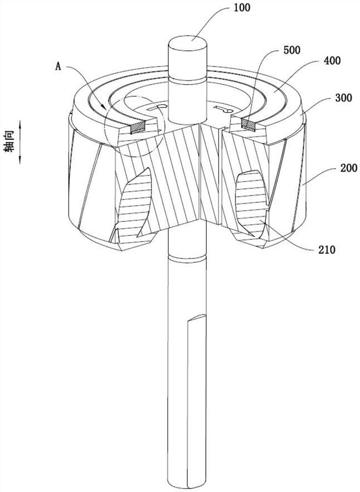
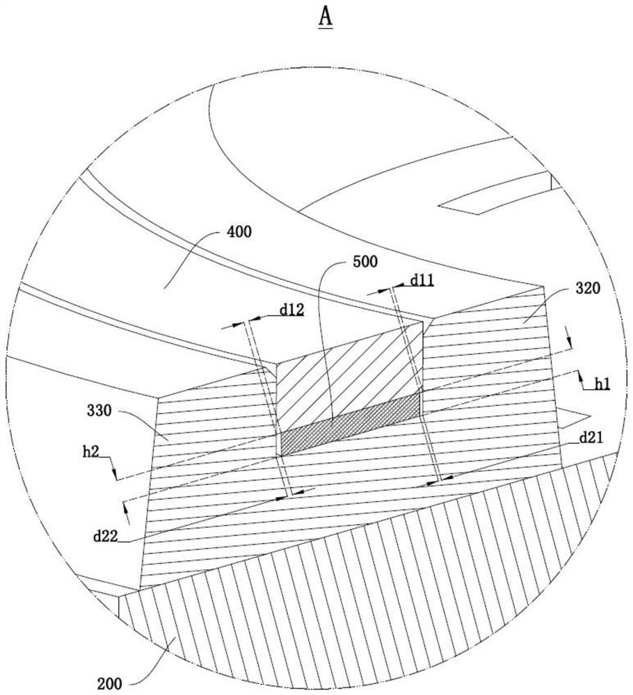
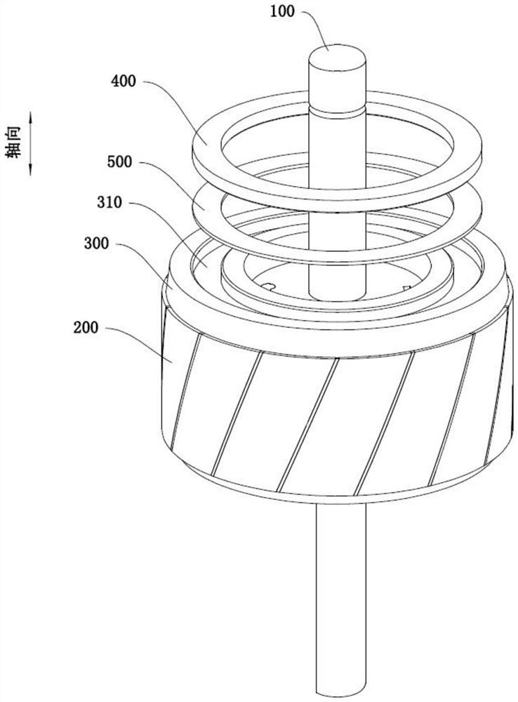
The invention discloses a rotor, a motor and a household appliance. The rotor comprises a rotating shaft, an iron core, an end ring, a magnet and a shielding part. The iron core is wound on the peripheral wall of the rotating shaft, the end ring is located at one end of the iron core in the axial direction of the rotating shaft, and a groove is formed in the end, away from the iron core, of the end ring. The magnet is mounted in the groove; the shielding part is made of a magnetic conductive material, the shielding part is installed in the groove and located on the side, facing the iron core, of the magnet, and due to the fact that the magnetic conductivity of the shielding part is far larger than that of air, more magnetic lines, penetrating through the groove, of a rotor magnetic field can pass through the shielding part to form a closed loop. Therefore, the influence of the rotor magnetic field on the magnetic field of the magnet is reduced, the interference of harmonic waves on the magnetic field induction device is reduced, the detection precision of the magnetic field induction device on the magnetic field of the magnet is improved, and the speed regulation precision of the motor is improved.

Description

technical field [0001] The invention relates to the technical field of motors, in particular to a rotor, a motor and household appliances. Background technique [0002] The AC motor with PG (Pulse Generator, pulse generator) speed regulation usually has a magnetic ring on the rotor. The magnetic ring is installed at the position of the rotor bearing, and a Hall sensor is arranged above the magnetic ring. The Hall sensor senses the magnetic field of the magnetic ring. Change, obtain the speed signal of the rotor, and then feed the signal back to the whole machine to realize the speed adjustment. However, the axial space occupied by the magnetic ring is relatively large, and the power density of the motor cannot be increased under the condition of a certain installation size limitation. [0003] In the related technology, the magnetic ring is installed on the rotor core to save axial space, but the magnetic field of the rotor will affect the magnetic field distribution of the...

Claims


Application Information

Patent Timeline
Patent Type & Authority Applications(China)
IPC IPC(8): H02K11/215H02K13/00H02K17/16
CPCH02K17/165H02K11/215H02K13/00H02K2213/03
Inventor 李伟吴迪陈松勇甘峰
Owner GUANGDONG WELLING ELECTRIC MACHINE MFG
Learn More