Method for removing electrolytic capacitor of boost converter and modified boost converter

A technology of boost converter and electrolytic capacitor, applied in the field of boost converter, can solve the problems of low reliability, difficulty of boost converter to meet industrial application, short service life, etc.

Active Publication Date: 2021-08-24
GUANGDONG UNIV OF TECH
View PDF6 Cites 0 Cited by
  • Summary
  • Abstract
  • Description
  • Claims
  • Application Information

AI Technical Summary

Problems solved by technology

[0003] The present invention provides a method for removing electrolytic capacitors of a boost converter and transforming a boost converter, which are used to solve the problem of using electrolytic capacitors in existing boost converters , has the defects of short service life, large volume and low reliability, which makes it difficult for the boost converter with electrolytic capacitor to meet the technical problems of practical industrial application requirements

Method used


Image

  • Method for removing electrolytic capacitor of boost converter and modified boost converter
  • Method for removing electrolytic capacitor of boost converter and modified boost converter
  • Method for removing electrolytic capacitor of boost converter and modified boost converter

Examples


Embodiment 1

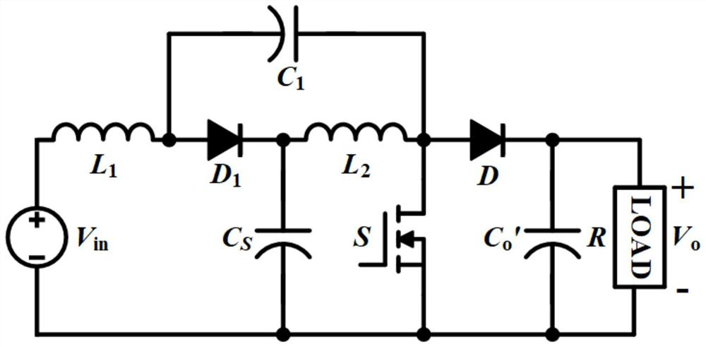
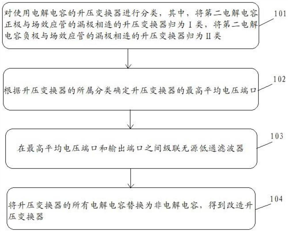
[0042] For ease of understanding, the embodiment of the present invention uses a quasi-Z source boost converter as an example to illustrate the process of removing the electrolytic capacitor of the boost converter. see Figure 2 to Figure 5 , an embodiment of a method for removing electrolytic capacitors of a boost converter provided by the present invention, the method is applied to include the first electrolytic capacitor C 1 , the second electrolytic capacitor C s , the third electrolytic capacitor C' 0 , the first inductance L 1 , the second inductance L 2 , the first diode D, the second diode D 1 , the voltage source Vin, the switch tube S and the boost converter of the load R;

[0043] The first inductance L 1 One end is connected to the anode of the voltage source Vin, the first inductor L 1 The other end is connected to the second diode D 1 anode of the second diode D 1 The cathode of the second inductor L is connected 2 One end of the second inductor L 2 Th...

Embodiment 2

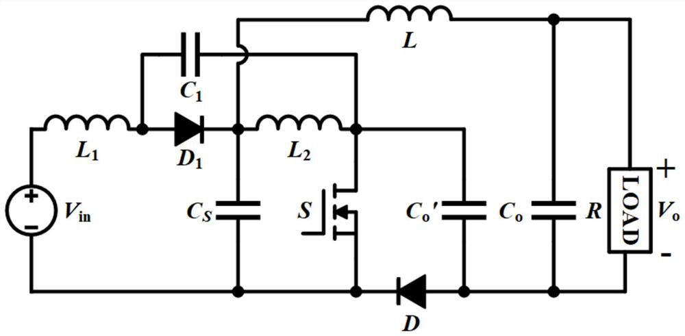
[0063] The present invention provides an embodiment of a modified boost converter. The modified boost converter in the embodiment of the present invention is improved by removing the electrolytic capacitor of the boost converter in Embodiment 1.

[0064] The formula for calculating the output voltage at the output port of the modified boost converter is:

[0065]

[0066] Among them, V o is the average output voltage, is the average capacitor voltage of the second electrolytic capacitor CS, is the average capacitor voltage of the third electrolytic capacitor C0, and D is the duty cycle of the field effect transistor.

[0067] The formula for calculating the output voltage ripple amplitude of the modified boost converter is:

[0068]

[0069] Among them, Δv o is the output voltage ripple amplitude, L is the inductance value of the passive low-pass filter inductor, C o is the capacitance value of the passive low-pass filter inductor, f s is the switching frequency ...


PUM

PropertyMeasurementUnit
Inductance valueaaaaaaaaaa
Capacitanceaaaaaaaaaa
Inductance valueaaaaaaaaaa

Abstract

The present invention discloses a method for removing an electrolytic capacitor of a boost converter and a modified boost converter. The method comprises the following steps: classifying the boost converters using electrolytic capacitors, classifying the boost converters of which the positive electrode of a second electrolytic capacitor Cs is connected with the drain electrode of a field-effect tube into a class I, classifying the boost converter for connecting the negative electrode of the second electrolytic capacitor Cs and the source electrode of the field-effect tube into class II; determining the highest average voltage port of the boost converter according to the classification of the boost converter; cascading a passive low-pass filter between the highest average voltage port and the output port; and replacing all electrolytic capacitors of the boost converter with non-electrolytic capacitors to obtain a modified boost converter. The boost converter with the electrolytic capacitor solves the technical problem that the existing boost converter with the electrolytic capacitor has the defects of short service life, large size and low reliability due to the use of the electrolytic capacitor, so that the boost converter with the electrolytic capacitor is difficult to meet the requirements of actual industrial application.

Description

technical field [0001] The invention relates to the technical field of boost converters, in particular to a method for removing electrolytic capacitors of a boost converter and transforming a boost converter. Background technique [0002] A boost converter, also known as a boost converter or a boost chopper, is a DC-DC converter that can boost voltage, and its output (load) voltage will be higher than the input (power) voltage. The structure of the traditional quasi-Z source DC-DC boost converter is as follows: figure 1 As shown, most of the existing boost converter capacitors use electrolytic capacitors, and the life of electrolytic capacitors is shorter than that of other devices in boost converters. Therefore, the life of boost converters is often determined by the life of electrolytic capacitors . In addition, the large size and low reliability of electrolytic capacitors make it difficult for a step-up converter with electrolytic capacitors to meet the requirements of ...

Claims


Application Information

Patent Timeline
IPC IPC(8): H02M3/156H02M1/14
CPCH02M3/156H02M1/14
Inventor 张桂东陈伟琛
Owner GUANGDONG UNIV OF TECH
Why Eureka
Try Eureka