Side dish adding mechanism and working method

A working method and technology for side dishes, applied in the field of kitchen supplies, can solve the problems of adding and destroying side dishes, and achieve the effects of low difficulty, low failure rate and simple operation

Pending Publication Date: 2021-08-27
AUBO BEIJING ROBOTICS TECH CO LTD
View PDF1 Cites 0 Cited by
  • Summary
  • Abstract
  • Description
  • Claims
  • Application Information

AI Technical Summary

Problems solved by technology

[0003] In order to solve the problem in the prior art that the side dishes are destroyed when they are added, the present invention provides a side dish adding mechanism and working method that maintain the integrity of the side dishes

Method used


Image

  • Side dish adding mechanism and working method
  • Side dish adding mechanism and working method
  • Side dish adding mechanism and working method

Examples


Embodiment 1

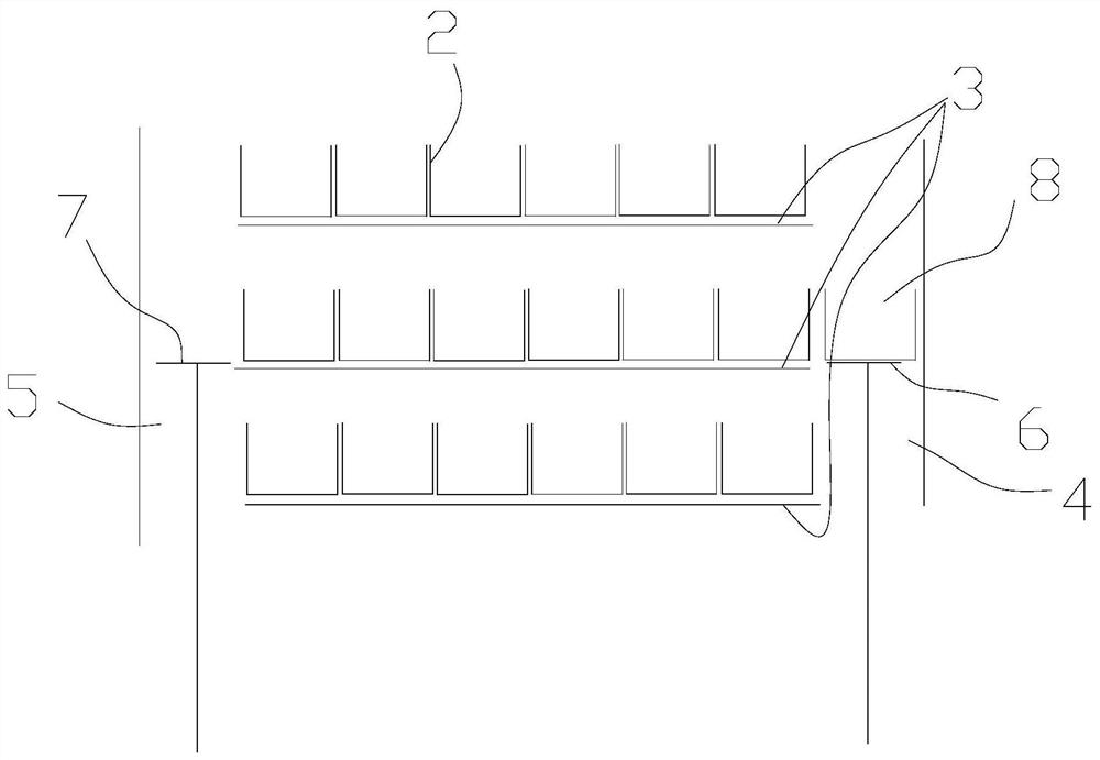
[0045] like figure 1 , the first channel 4 or the second channel 5 is set in the middle of the slideway 3, and the pick-and-place material level 8 is set at a certain position on the slideway 3, through the first lifting pallet 6, the second lifting pallet 7 and the pushing The mechanism pushes the material grid 2 filled with side dishes to the pick-and-place material position 8.

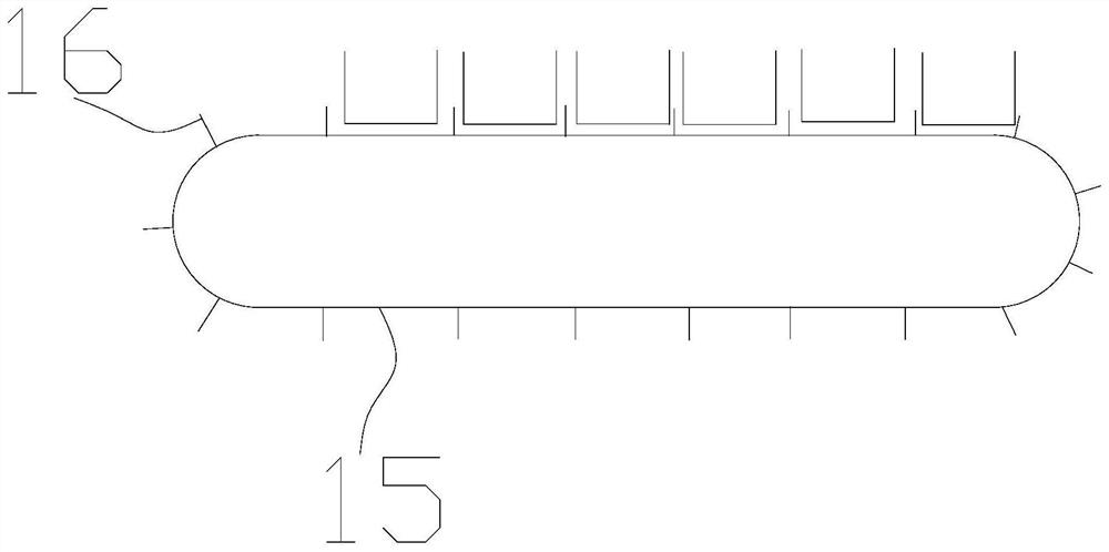
[0046] When the first channel 4 or the second channel 5 is located in the middle of the slideway 3, if the pushing mechanism adopts the form of a cylinder, etc., the installation is difficult and interference is likely to occur. The pushing of the material grid 2 can be in the form of a fixed push plate 16 on the chain 15 ,like figure 2 , directly installed above or below the slideway 3.

Embodiment 2

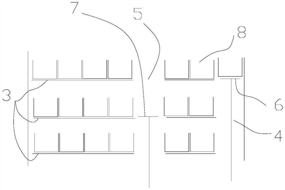
[0048] like image 3 , the first passage 4 is arranged at the first end of the slideway 3 , and the second passageway 5 is arranged at the second end of the slideway 3 . The number of slideway 3 layers is 3 layers and above, and the pick-and-place material level 8 is set at the intersection of the extension area of ​​the first channel 4 and the middle layer slideway 3, so that the passages of the upper layer and the lower layer can be taken and placed according to the layer. 8 Push the material grid 2 containing side dishes, such as pushing the upper layer first, and then pushing the lower layer.

Embodiment 3

[0050] As an embodiment of the present invention, the slideway 3 layers are two layers, such as Figure 4 , the pick-and-place material level 8 is set at the intersection of the first channel 4 and the extension area of ​​the upper slideway 3 .

[0051] like Figure 5-6 , the first lifting pallet 6 and the second lifting pallet 7 are all connected with a lifting cylinder 9, and the first lifting pallet 6 and the second lifting pallet 7 are fixed with the piston rod of the lifting cylinder 9 at the corresponding position. The pushing mechanism that is positioned at the slideway 3 of upper floor comprises the first pushing cylinder 10 and the first pushing plate 11 that is fixed with the piston rod of the first pushing cylinder 10, and the pushing mechanism that is positioned at the slideway 3 of lower floor comprises the second pushing cylinder 12 and with The second push plate 13 that the piston rod of the second push cylinder 12 is fixed, the first push cylinder 10 is arrang...


PUM


Abstract

The invention relates to the technical field of kitchen supplies, in particular to a side dish adding mechanism and a working method. The side dish adding mechanism comprises a frame body and material lattices used for containing side dishes, the frame body is provided with a plurality of layers of sliding ways for the material lattices to slide, and the frame body is further provided with a first channel perpendicular to the sliding ways and at least one second channel; a first lifting supporting plate is arranged in the first channel in a lifting mode, a second lifting supporting plate is arranged in the second channel in a lifting mode, the first lifting supporting plate and the second lifting supporting plate are used for lifting the material lattices to ascend and descend in the channels, and each layer of sliding way is further provided with a pushing mechanism used for pushing the material lattices to the first lifting supporting plate or the second lifting supporting plate. According to the side dish adding mechanism, the side dishes only need to be placed in the material lattices in bulk, then the lattices grids are conveyed, food materials do not need to be additionally bundled or stringed, the operation is easy, and the difficulty is low.

Description

technical field [0001] The invention relates to the technical field of kitchen supplies, in particular to a side dish adding mechanism and working method. Background technique [0002] Manually boiled noodles or pasta vending machines generally use side dishes such as vegetables, meat and meatballs in the cooking process. In the prior art, the side dishes of manually cooked noodles are piled up together, which is inconvenient to take. Automatic vending machines The operation process of side dishes is more complicated, as the patent No. CN207264504U discloses a kind of ready-made pasta automatic vending machine, wherein the food unit storage compartments include several groups of storage compartments and storage tanks, and three food unit storage compartments are arranged, respectively. There are customers' daily favorite foods such as beef brisket, meatballs and green vegetables. The storage compartment includes a column-shaped storage space, a pin hole arranged on the upper...

Claims


Application Information

Patent Timeline
Patent Type & Authority Applications(China)
IPC IPC(8): A47J36/00A47J27/00A47J47/01
CPCA47J27/00A47J36/00A47J47/01
Inventor 魏洪兴郭奎
Owner AUBO BEIJING ROBOTICS TECH CO LTD
Why Eureka
Try Eureka