Supercharge Your Innovation With Domain-Expert AI Agents!

Integrated U-rib laser cleaning production line structure

A laser cleaning and production line technology, applied in the field of laser cleaning, can solve the problems of unstable grinding effect, easy damage to workpieces, low operation efficiency, etc., and achieve the effect of good cleaning quality, good surface consistency, and improved production efficiency.

Inactive Publication Date: 2021-08-27
WUHAN FARLEYLASERLAB CUTTING SYST ENG
View PDF7 Cites 1 Cited by
  • Summary
  • Abstract
  • Description
  • Claims
  • Application Information

AI Technical Summary

Problems solved by technology

During the period, the workpiece needs to be turned over repeatedly. The labor intensity of the workers is extremely high, and the quality of the grinding is not stable, and the work efficiency is low. At the same time, the dust and noise generated by the grinding will directly threaten the health of the workers.
[0005] The existing special U-rib grinding equipment adopts the contact mechanical grinding method, which inevitably brings mechanical vibration and noise, etc., resulting in unstable grinding effect, easy damage to the workpiece, serious noise pollution, poor equipment stability and many other problems
[0006] The existing special U-rib grinding equipment needs manual assistance to locate the U-rib area to be polished before grinding, and cannot perform adaptive adjustment according to the difference in the shape and size of the U-rib
In actual production, there is a certain range of manufacturing errors in the U-rib parts, resulting in poor consistency of the grinding effect. It is often necessary to manually re-grind the poorly ground parts, which seriously affects the work efficiency.

Method used


Image

  • Integrated U-rib laser cleaning production line structure
  • Integrated U-rib laser cleaning production line structure
  • Integrated U-rib laser cleaning production line structure

Examples


Embodiment Construction

[0034] The following will clearly and completely describe the technical solutions in the embodiments of the present invention with reference to the accompanying drawings in the embodiments of the present invention. Obviously, the described embodiments are only some, not all, embodiments of the present invention. Based on the embodiments of the present invention, all other embodiments obtained by persons of ordinary skill in the art without making creative efforts belong to the protection scope of the present invention.

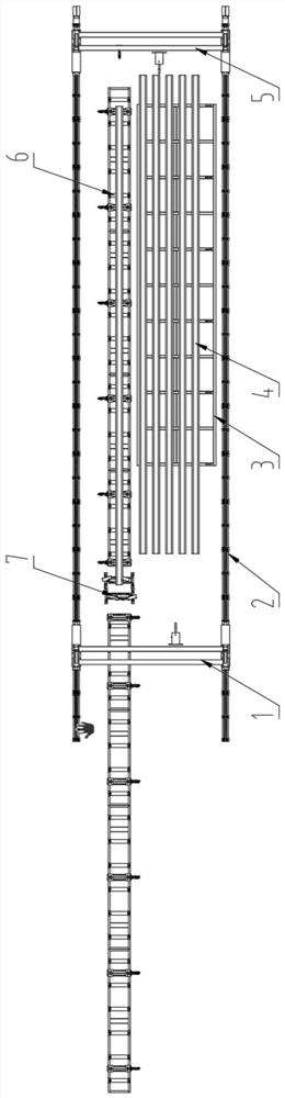
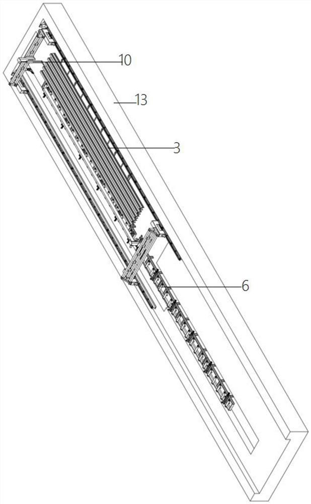
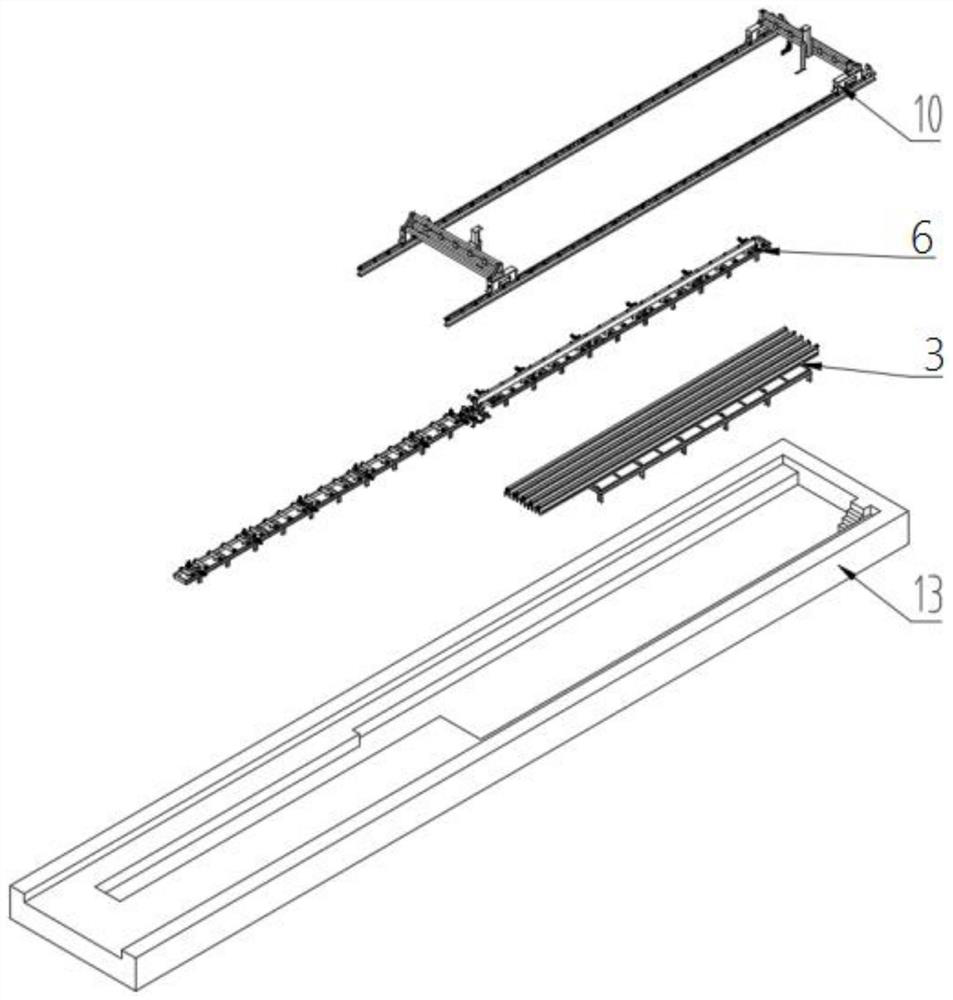
[0035] Such as Figure 1-Figure 10 , the embodiment of the present invention provides an integrated U-rib laser cleaning production line structure, including a ground rail 2, a U-rib storage stand 3 for placing U-rib parts 4, and a conveying line body 6 for transporting U-rib parts 4. The ground rail 2 is provided with a gantry type loading and unloading device assembly 10, and the gantry type loading and unloading device assembly 10 is used to send the U-rib ...


PUM


Abstract

The invention provides an integrated U-rib laser cleaning production line structure. The integrated U-rib laser cleaning production line structure comprises a ground rail, a U-rib storage rack used for containing U-rib parts and a conveying line body used for conveying the U-rib parts, wherein a gantry type feeding and discharging device assembly is arranged on the ground rail and is used for conveying the U-rib parts from the U-rib storage rack to the conveying line body; and a laser cleaning device is arranged on a conveying line of the conveying line body. The integrated U-rib laser cleaning production line is an automatic production line which is highly integrated and controlled, continuous welding bead cleaning of U-rib parts can be achieved, the production efficiency is improved, dust and vibration are avoided in the production process, and the integrated U-rib laser cleaning production line has the characteristics of non-contact, no grinding, mute and environmental-friendly effects. The laser beam accessibility can be fully utilized, the influence of U-rib part manufacturing errors on the cleaning quality is effectively made up, and the good cleaning quality is achieved. The U-rib weld bead cleaned by the production line is attractive in appearance and better in surface consistency.

Description

technical field [0001] The invention relates to the technical field of laser cleaning, in particular to an integrated U-rib laser cleaning production line structure. Background technique [0002] The common orthotropic plate units on large steel structure bridges are welded by U ribs and panels, which have the advantages of light weight and high load capacity. In order to ensure the welding quality of the orthotropic plate unit, the weld bead area of ​​the U-rib needs to be cleaned before being welded to the panel to remove floating rust, scale, paint, oil and other attachments on the surface. In order to ensure the cleaning quality, it is usually necessary to use manual or special equipment to mechanically polish the area of ​​the U rib to be welded. [0003] The traditional manual grinding of U-rib parts requires a lot of physical strength, the grinding quality is unstable and the work efficiency is low, and the dust and noise generated will directly threaten the health o...

Claims


Application Information

Patent Timeline
Patent Type & Authority Applications(China)
IPC IPC(8): B08B7/00B08B13/00
CPCB08B7/0042B08B13/00
Inventor 胡纯靳伦平黄斅李家军袁康吴苶
Owner WUHAN FARLEYLASERLAB CUTTING SYST ENG
Features
  • R&D
  • Intellectual Property
  • Life Sciences
  • Materials
  • Tech Scout
  • Unparalleled Data Quality
  • Higher Quality Content
  • 60% Fewer Hallucinations
Learn More