A maintainable shed structure
A technology for shed holes and ladders, applied in protective equipment, buildings, etc., can solve problems such as easy accumulation of falling rocks and unmaintainable tops of shed holes, achieve good stability and safety, reduce the impact of falling rocks, and facilitate maintenance
- Summary
- Abstract
- Description
- Claims
- Application Information
AI Technical Summary
Problems solved by technology
Method used
Image
Examples
Embodiment 1
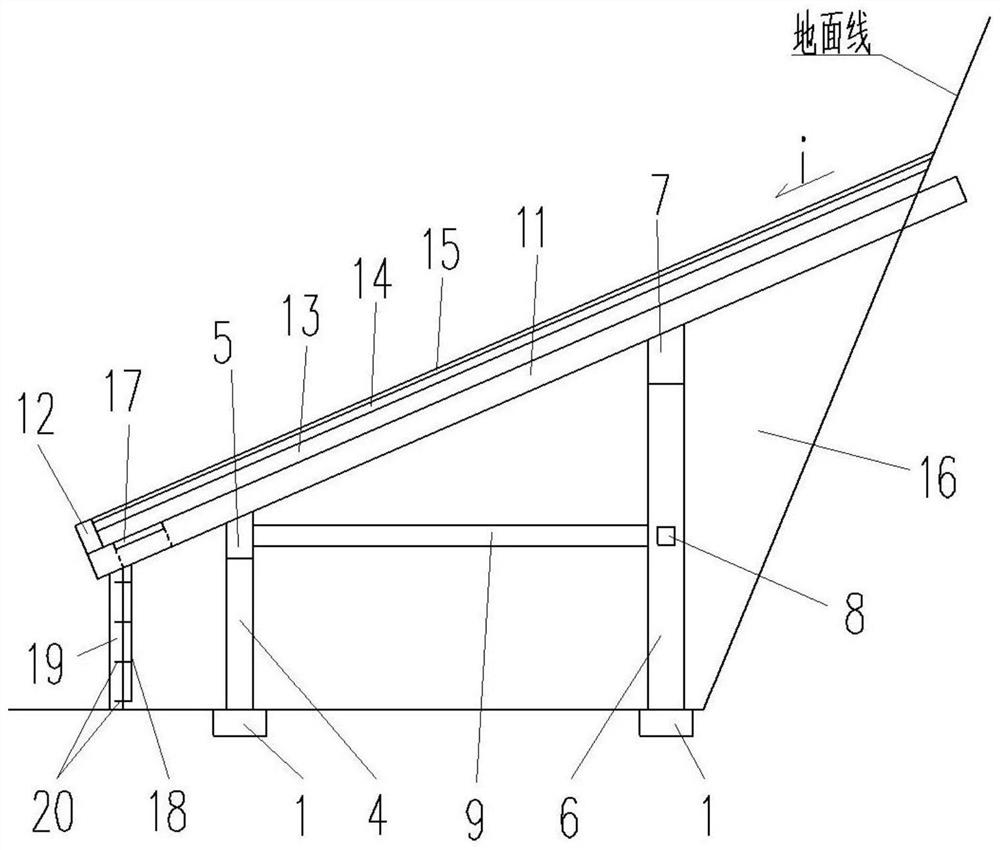
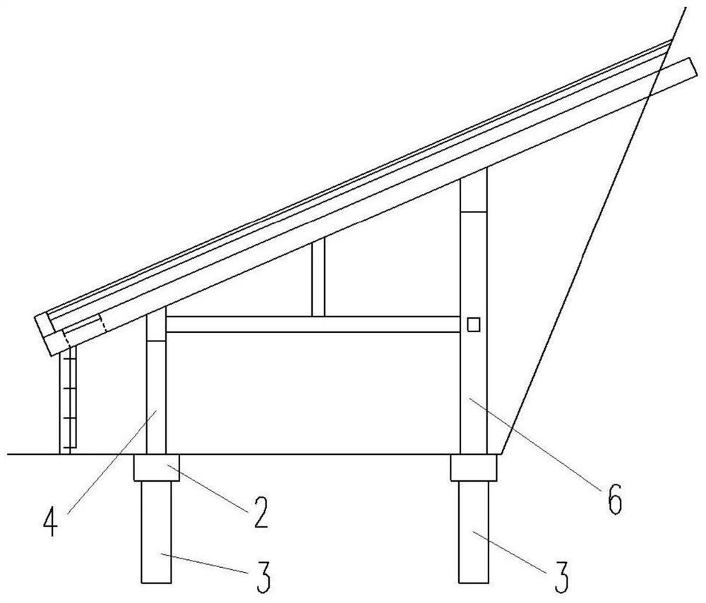
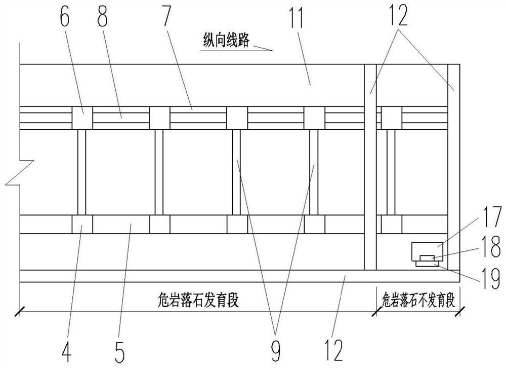
[0045] This embodiment provides a maintainable shed structure, such as Figure 1-Figure 3 As shown, in a preferred embodiment, it includes a plurality of longitudinally spaced inner columns 6 arranged on the side of the mountain, a plurality of longitudinally spaced outer columns 4 located on the outside of the inner column 6, and a plurality of inner columns 6 at the same time. The inner side member 7 fixedly connected, the outer side member 5 fixedly connected to the plurality of outer columns 4 at the same time, and the top plate 11 provided on the top of the inner side member 7 and the outer side member 5 and fixed to both at the same time.
[0046] Among them, the inner side of the shed has a backfill area 16, and the inner side of the shed is generally backfilled with concrete, and it can also be backfilled with masonry rubble if it is convenient to obtain local materials.
[0047] The roof 11 completely covers the developed section of dangerous rock and rockfall and ext...
Embodiment 2
[0056] The structure and principle of this embodiment are basically the same as those of the first embodiment, the difference is that the structure of the climbing ladder 18 is different. like Figure 5-Figure 7 As shown, in this embodiment, the climbing ladder 18 is a foldable structure, the lower end of the climbing ladder 18 is provided with a non-slip rubber pad, the upper end of the climbing ladder 18 is connected with a connecting block 21 through the rotation of the shaft, and the end of the connecting block 21 away from the climbing ladder 18 is connected to the connecting block 21. The ladder wall 19 is rotatably connected, for example, the upper end of the ladder wall 19 is fixedly connected with a connection seat, and the connection block 21 is connected in rotation with the connection seat through a rotating shaft.
[0057] Figure 5-Figure 7 The shown climbing ladder 18 only schematically depicts eight pedals. In practice, the height of the climbing ladder 18 and...
Embodiment 3
[0063] The structure and principle of this embodiment are basically the same as those of the second embodiment, except that, Figure 8 and Figure 9 As shown, in this embodiment, the ladder 18 is further connected with a plurality of collapsible support rods 26 located between the ladder 18 and the ladder wall 19, and the lower ends of the support rods 26 are also provided with anti-skid rubber pads. like Figure 8 As shown, when the climbing ladder 18 is in the unfolded state, all the support rods 26 are fully extended. At this time, the support rods 26 are inclined vertically or slightly backward to the left, and the lower ends of the support rods 26 are in contact with the ground. support.
[0064] After using the climbing ladder 18, push the climbing ladder 18 inward, and the leftmost support rod 26 is in conflict with the climbing ladder wall 19. During the process of continuing to push the climbing ladder 18 inward, under the action of the climbing ladder wall 19, the ...
PUM
 Abstract
Description
Claims
Application Information
 - R&D
- Intellectual Property
- Life Sciences
- Materials
- Tech Scout
- Unparalleled Data Quality
- Higher Quality Content
- 60% Fewer Hallucinations
Browse by: Latest US Patents, China's latest patents, Technical Efficacy Thesaurus, Application Domain, Technology Topic, Popular Technical Reports.
© 2025 PatSnap. All rights reserved.Legal|Privacy policy|Modern Slavery Act Transparency Statement|Sitemap|About US| Contact US: help@patsnap.com


