Variable-liquid-level periodic uniform-flow water outlet device

A liquid level and water outlet technology, which is applied to water supply devices, waterway systems, drainage structures, etc., can solve problems such as inapplicability, large changes in water outlet flow, and reduced discharge flow, so as to reduce power costs and maintenance costs. Anticipated impact, dynamics provide a steady effect

Pending Publication Date: 2021-08-27
上海同晟环保科技有限公司
View PDF0 Cites 2 Cited by
  • Summary
  • Abstract
  • Description
  • Claims
  • Application Information

AI Technical Summary

Problems solved by technology

[0004] 1) Utilizing the action of gravity, through the low-level valve piping system or perforated orifice plate, etc., the stored water to be discharged is released. Although no external power is required, as the water level in the water storage space decreases, the discharge flow will decrease. Continuously decreasing, the effluent flow rate changes greatly, and this method is not applicable to the environment that requires a long period of time to release the water volume slowly and evenly;
[0005] 2) Utilize external kinetic energy to drive water pumps or other power devices combined with water level control facilities to lift or transport water out of the water body. Although the water volume in the storage space can be discharged in a planned and controlled manner with a stable flow rate, in many environments, It is difficult to provide a stable power source and electromechanical equipment; even if there is a power source, it will be difficult to apply and promote because of the complexity of engineering implementation and operation and maintenance
[0006] 3) Periodic drainage cannot be realized, and it cannot be used in occasions that require periodic equal flow drainage

Method used


Image

  • Variable-liquid-level periodic uniform-flow water outlet device
  • Variable-liquid-level periodic uniform-flow water outlet device
  • Variable-liquid-level periodic uniform-flow water outlet device

Examples


Embodiment Construction

[0036] The present invention is described in further detail now in conjunction with accompanying drawing. These drawings are all simplified schematic diagrams, which only illustrate the basic structure of the present invention in a schematic manner, so they only show the configurations related to the present invention.

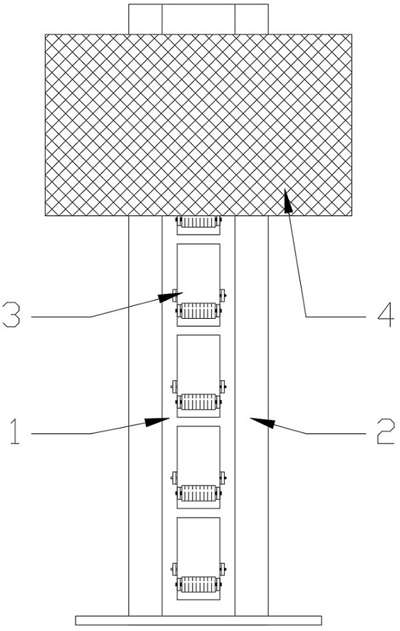
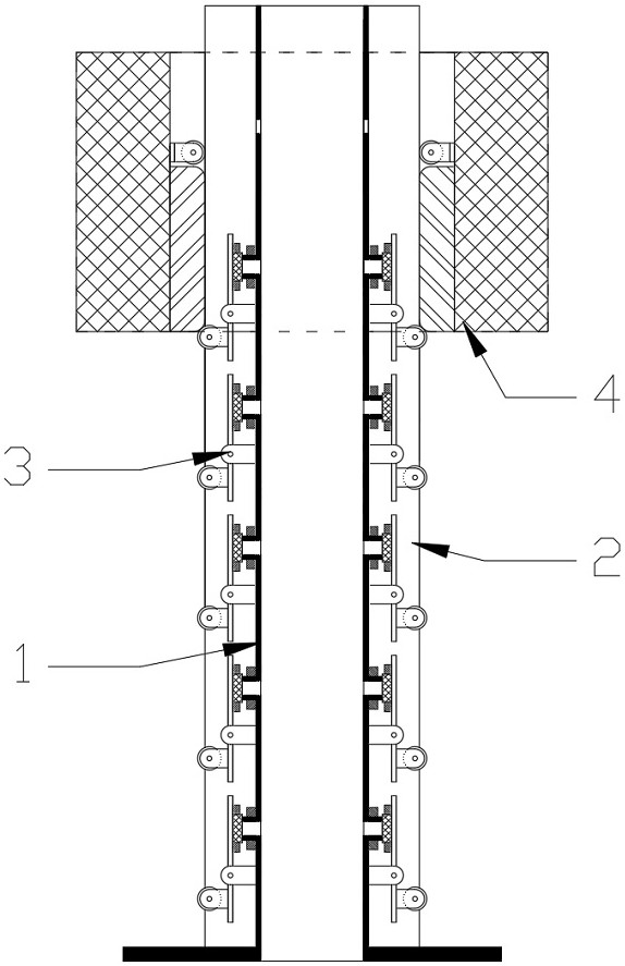
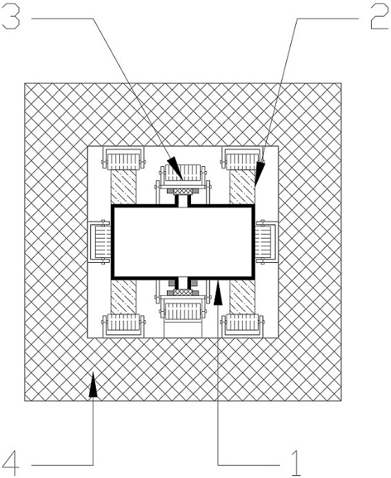
[0037] Such as Figure 1-12 Shown is a variable liquid level periodic water outlet device provided by the present invention, including an outlet pipe 1, a guide rail 2, a magnetic valve 3 and a floating body trigger cylinder 4; its feature is that the outlet pipe 1 is installed vertically on Inside the water tank, the bottom end of the outlet pipe 1 communicates with the water outlet of the water tank, the guide rail 2 is installed on the radially outer side of the outlet pipe 1, and the magnetic valve 3 is provided with multiple valves installed on two opposite sides of the outlet pipe 1. and arranged equidistantly from top to bottom; the floating body trigg...


PUM


Abstract

The invention provides a variable-liquid-level periodic uniform-flow water outlet device. The variable-liquid-level periodic uniform-flow water outlet device comprises a flow outlet pipe, a guide rail, magnetic valves and a floating body triggering cylinders; the floating body triggering cylinders sequentially make contact with and push the magnetic valves at the corresponding positions to swing along with descending of the liquid level, so that transverse flow pipes at the corresponding positions are opened, the pushing force to the magnetic valves at the upper positions is cancelled to reset the transverse flow pipes, so that water flows out of a water outlet of a water tank periodically while the liquid level continuously descends, drainage is stable, and periodic equal-flow drainage can be achieved. The floating body triggering cylinders sequentially make contact with and push the magnetic valves at the corresponding positions to swing along with descending of the liquid level, so that the transverse flow pipes at the corresponding positions are opened to achieve periodical uniform flow drainage, an external power source does not need to be additionally provided, power supply is stable, and the power cost and the maintenance cost are effectively reduced; and periodic uniform water outlet can be achieved, the application range is wide, uniform and stable water outlet is achieved, and meanwhile the unexpected influence possibly caused by continuous water outlet is avoided.

Description

technical field [0001] The invention relates to the technical field of equal outflow of water, in particular to a device for equal outflow of water with variable liquid level period. Background technique [0002] The construction of a sponge city means that the city can absorb, store, infiltrate and purify water when it rains like a sponge, and "release" the stored water when needed; In order to achieve the purpose of reducing runoff peak flow, delaying runoff peak time, and accurately planning the amount of water storage, it is necessary to effectively control the flow of water in the storage space. [0003] In order to achieve the above-mentioned goal of controlling the water outlet flow, the following methods are often used in the prior art: [0004] 1) Utilizing the action of gravity, through the low-level valve piping system or perforated orifice plate, etc., the stored water to be discharged is released. Although no external power is required, as the water level in th...

Claims


Application Information

Patent Timeline
Patent Type & Authority Applications(China)
IPC IPC(8): E03F5/10E03F3/04G05D7/03
CPCE03F3/04E03F5/107G05D7/03
Inventor 穆毅王坚伟易威陈繁曹树东郭志浩邱成陈勇刘飞杭添
Owner 上海同晟环保科技有限公司
Why Eureka
Try Eureka