
Buffering structure of earthquake-avoiding safety cabin
A buffer structure and safety technology, which is applied in the direction of earthquake resistance, building components, special buildings, etc., can solve the problems of insufficient safety performance of the shock-absorbing safety cabin, poor buffering effect, and too simple buffering mechanism, so as to reduce strong vibration and reduce Vibration, the effect of improving safety performance
- Summary
- Abstract
- Description
- Claims
- Application Information
AI Technical Summary
Problems solved by technology
Method used
Image

Examples
Embodiment 1
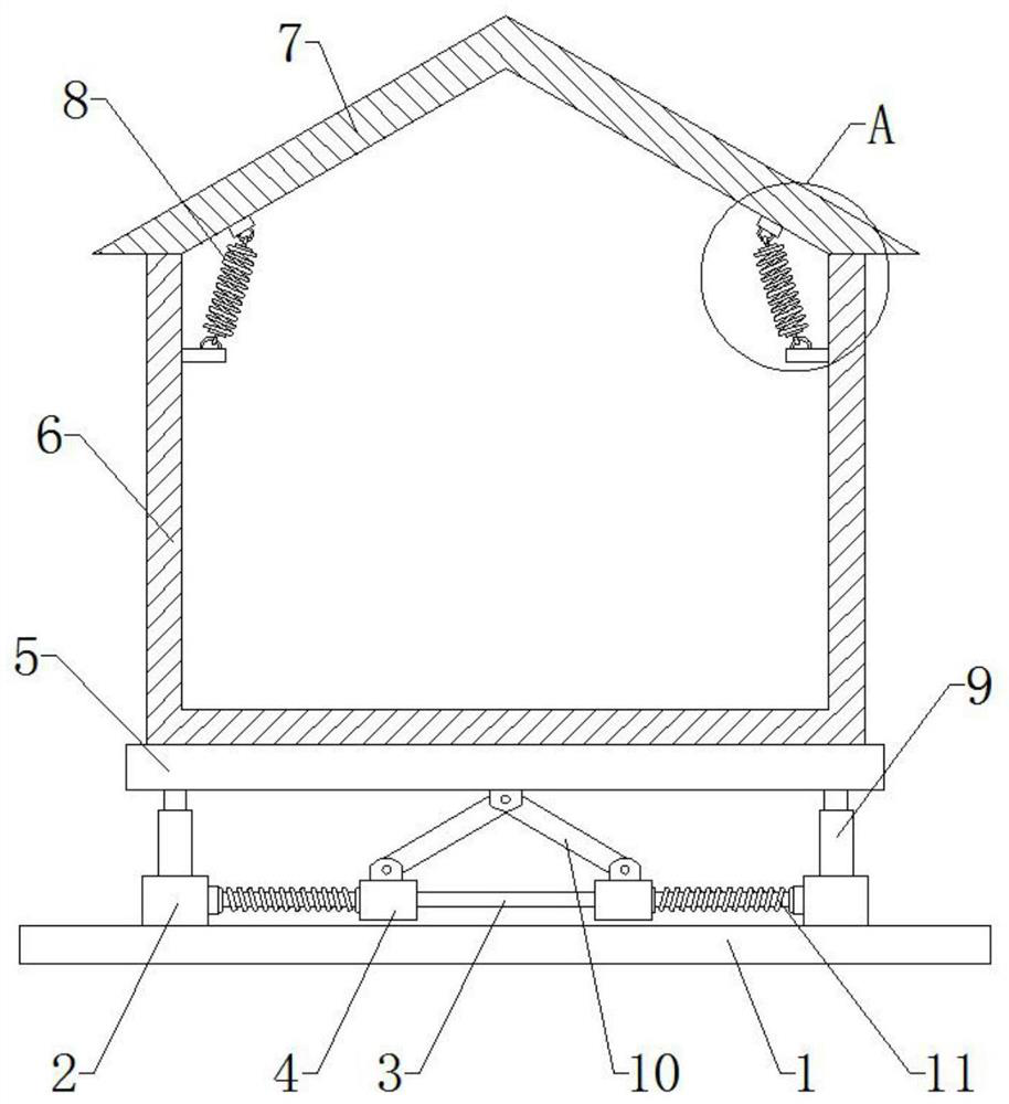
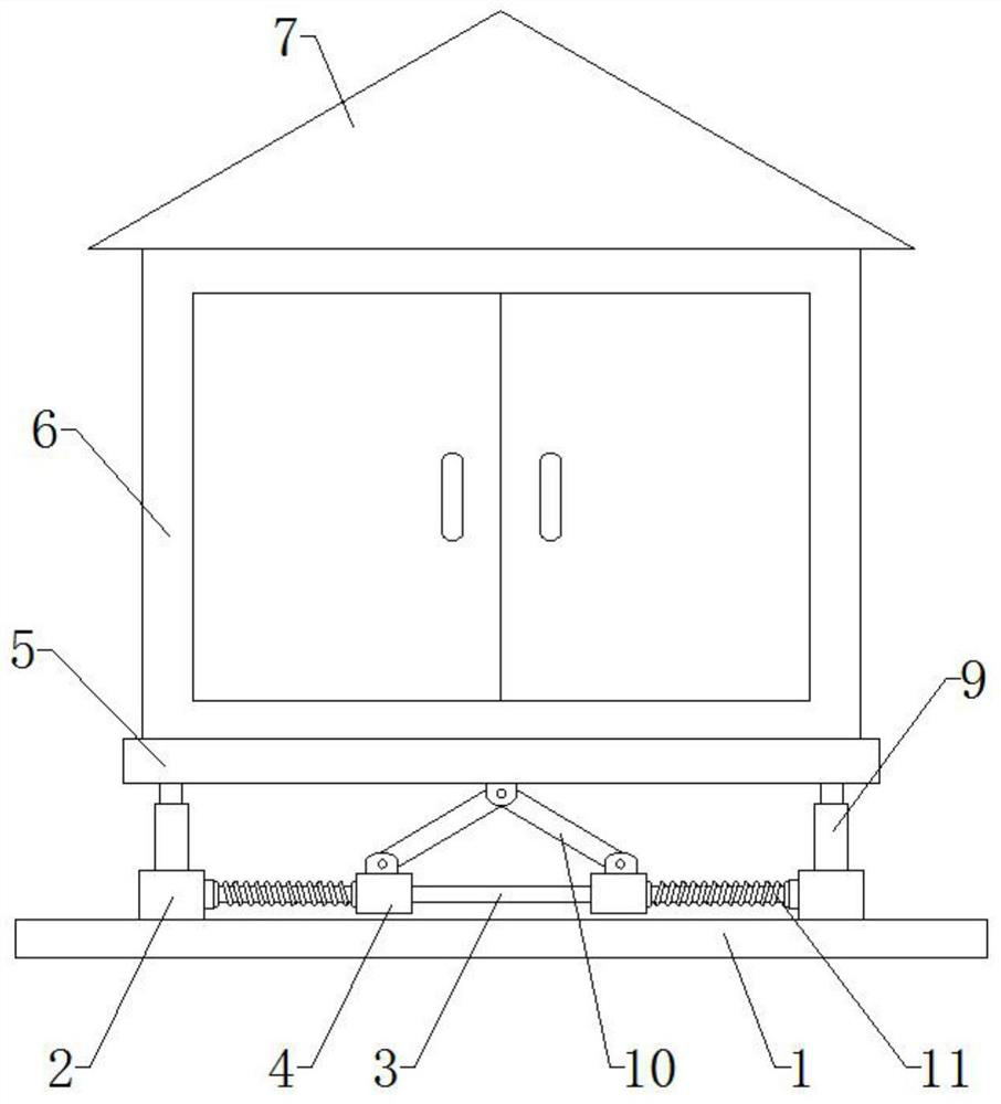
[0026] Embodiment 1: When the top plate 5 vibrates up and down, it drives the rotating rod 10 to rotate, and the rotating rod 10 drives the sliding sleeve 4 to slide slightly. The telescopic spring 11 can provide a certain elastic force and buffer force, which ensures sufficient buffering for the mounting plate 8 force.
Embodiment 2
[0027] Embodiment 2: Gas springs 9 are fixedly connected to the fixing seats 2 , the top plate 5 is located above the bottom plate 1 , and the bottom of the top plate 5 is fixedly connected to the top of the gas spring 9 . The gas spring 4 also plays a certain damping effect, thereby effectively reducing the strong vibration of the safety chamber 6.
Embodiment 3
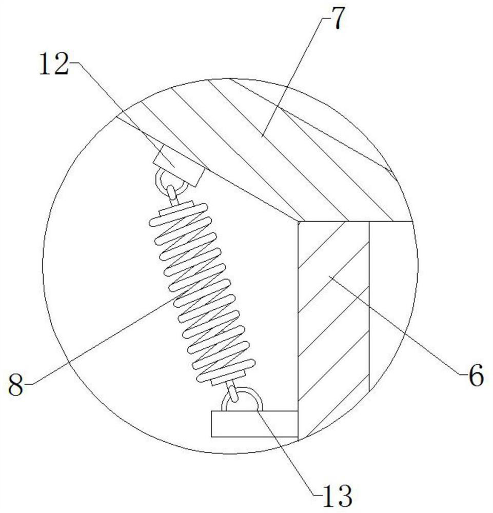
[0028] Embodiment three: the first spring seat 12 is provided on the inner walls of both sides of the roof 7, and the second spring seat 13 is provided above the inner walls of the two sides of the safety chamber 6, and the first spring seat 12 and the second spring seat 13 All have clasps. Both sides of the top in the safety chamber 6 are provided with damping springs 8, and the two ends of the damping springs 8 are provided with hooks, and the hooks match the clasps. The damping spring 8 can effectively relieve the resonance between the safety chamber 6 and the roof 7, and improves the safety of the safety chamber 6 body.
PUM
 Abstract
Description
Claims
Application Information