
Cylindrical battery roll core and manufacturing method thereof

A technology of cylindrical battery and manufacturing method, which is applied in the direction of secondary battery manufacturing, cylindrical shell battery/battery, secondary battery, etc., which can solve the problems of short circuit in the battery core and non-winding of tabs, etc., and reduce equipment and environment. Requirements, design solutions, novel effects of structural design

Pending Publication Date: 2021-08-27
SUZHOU PHYLION BATTERY
View PDF3 Cites 0 Cited by
  • Summary
  • Abstract
  • Description
  • Claims
  • Application Information

AI Technical Summary

Problems solved by technology

The deviation of the thickness of the pole piece results in that the tabs cut out by the invention cannot be wound in the specified area, and the deviation of the position of the tabs will cause the positive and negative semicircles to have overlapping tabs, so that the battery cells with the tabs can be flattened and welded. is short-circuited

Method used


Image

  • Cylindrical battery roll core and manufacturing method thereof
  • Cylindrical battery roll core and manufacturing method thereof
  • Cylindrical battery roll core and manufacturing method thereof

Examples


Embodiment 1

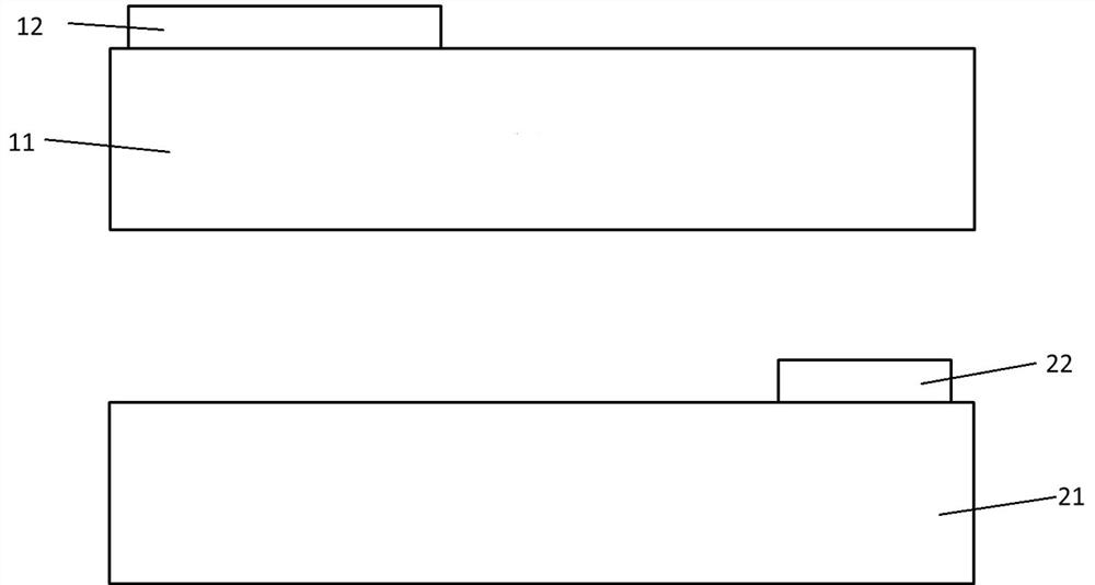
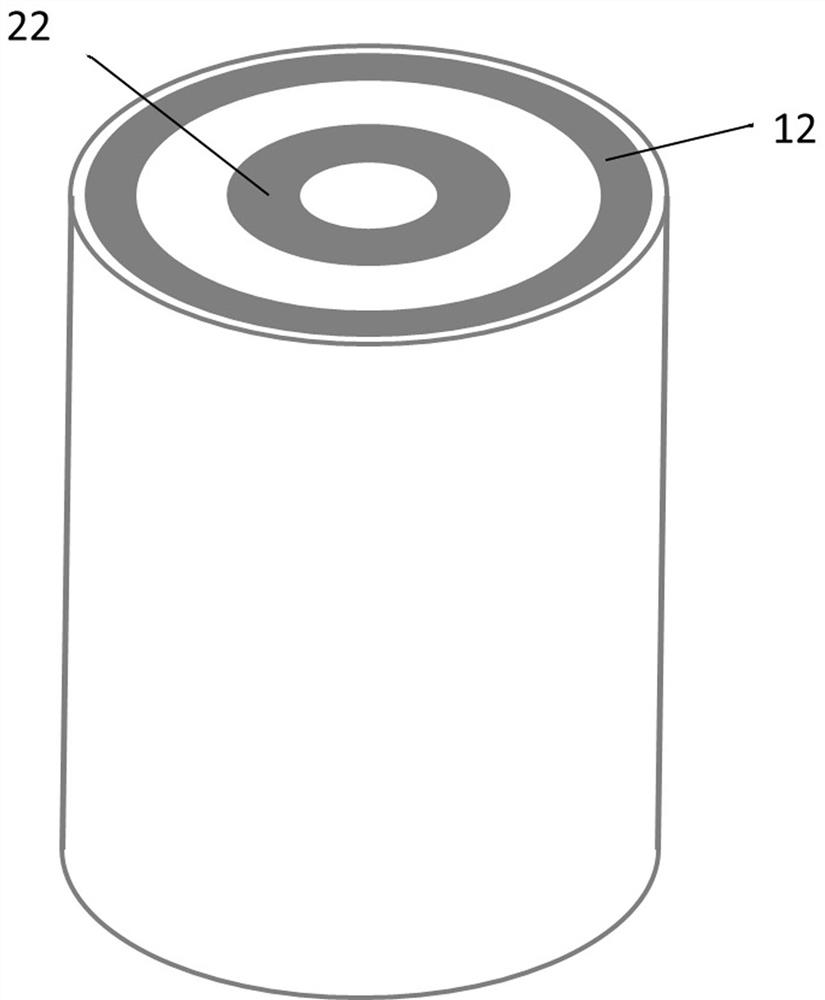
[0026] see figure 2 Shown is a schematic diagram of the overall structure of the cylindrical battery core of this embodiment, which is composed of a positive electrode sheet 11 , a separator, a negative electrode sheet 21 and a separator that are stacked and wound.

[0027] The battery pole piece is continuously coated, the coated area is used as the active material area, and the non-coated area is used as the tab. After the coating is completed, the pole piece is rolled to reach the designed compaction density. Subsequent sectioning into strips to form figure 1 The positive electrode sheet 11 and the negative electrode sheet 21 shown in , wherein the large rectangle is the coating area of ​​the positive electrode sheet 11, 12 is the positive electrode ear, and the positive electrode ear 12 is the remaining electrode ear after part of the electrode ear has been cut off; the negative electrode sheet 21 The middle and large rectangle is the coated area of ​​the negative elect...

Embodiment 2

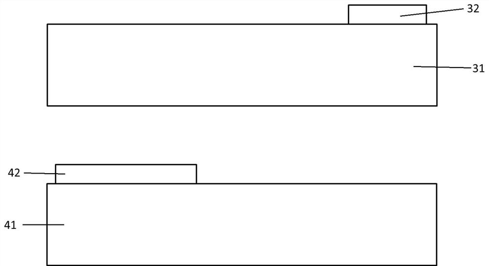
[0036] see Figure 4 Shown is a schematic diagram of the overall structure of the cylindrical battery core of this embodiment, which is composed of a positive electrode sheet 31 , a separator, a negative electrode sheet 41 and a separator that are stacked and wound.

[0037] The battery pole piece is continuously coated, the coated area is used as the active material area, and the non-coated area is used as the tab. After the coating is completed, the pole piece is rolled to reach the designed compaction density. Subsequent sectioning into strips to form image 3 The positive electrode sheet 31 and the negative electrode sheet 41 shown in , wherein the large rectangle is the coating area of ​​the positive electrode sheet 31, 32 is the positive electrode ear, and the positive electrode ear 32 is the remaining electrode ear after part of the electrode ear has been cut off; the negative electrode sheet 41 The middle and large rectangle is the coated area of ​​the negative elect...


PUM


Abstract

The invention discloses a cylindrical battery roll core which is formed by overlapping and winding a positive plate, a diaphragm, a negative plate and a diaphragm; the positive plate is provided with a positive tab, the negative plate is provided with a negative tab, and the positive tab and the negative tab are located on the same end face; and a distance is reserved between the positive tab of the positive plate and the negative tab of the negative plate in the length direction after the positive plate and the negative plate are overlapped, so that the positive tab of the positive plate and the negative tab of the negative plate form two non-overlapped annular structures after being wound. Through the ingenious design, the phenomenon that positive and negative tabs are overlapped is solved, the short circuit in the roll core is avoided, the requirements on equipment and environment are greatly reduced, and thus the labor cost is reduced.

Description

technical field [0001] The invention relates to the field of lithium ion battery manufacturing, in particular to a cylindrical battery winding core and a manufacturing method thereof. Background technique [0002] Cylindrical lithium-ion batteries adopt continuous coating without die-cutting and stacking processes, so the production efficiency of cylindrical batteries is high and the manufacturing cost is low. In addition, cylindrical batteries have incomparable advantages in terms of thermal expansion and contraction, anti-vibration and battery clamping and restraint. [0003] Chinese Invention Patent Application Publication No. CN112542641A discloses a cylindrical battery and its manufacturing method. By arranging the tab on one end surface of the winding core, the height of the winding core can be reduced to a certain extent, and at the same time, only one end of the shell can be The opening and sealing reduce the overall weight of the cylindrical battery. In the manufac...

Claims


Application Information

Patent Timeline
IPC IPC(8): H01M10/0525H01M10/0587H01M10/04H01M50/538
CPCH01M10/0525H01M10/0587H01M10/0422Y02P70/50Y02E60/10
Inventor 王永琛王正伟朱华君刘付召
Owner SUZHOU PHYLION BATTERY
Learn More