A strain-resistant clamp

A technology of tension-resistant clamps and drainage clamps, which is applied in the direction of overhead lines/cable equipment, adjusting/maintaining mechanical tension, instruments, etc.

Active Publication Date: 2022-04-12
FOGANG XINYUAN HENGYE CABLE TECH CO LTD
View PDF4 Cites 0 Cited by
  • Summary
  • Abstract
  • Description
  • Claims
  • Application Information

AI Technical Summary

Problems solved by technology

The tension clamps connect the shell body (clamp shell) to the electric tower through a pull rod or a hanging plate, which requires considerable strength. Most of the main tubes of the existing clamp shells are single-layer main tubes, which are not very good. Satisfies the harsh conditions of use of tension clamps

Method used


Image

  • A strain-resistant clamp
  • A strain-resistant clamp
  • A strain-resistant clamp

Examples


Embodiment 1

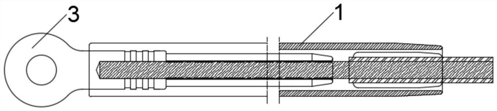
[0058] see Figure 1-5 , an embodiment provided by the present invention: a tension clamp, including a tension clamp, the tension clamp includes a main pipe 1, a steel anchor 3, the main pipe 1 is a hollow structure, the main pipe 1 One end is fixedly connected with the steel anchor 3, and the other end of the main pipe 1 is provided with a first lined aluminum tube 5 and a second lined aluminum tube 6, the first lined aluminum tube 5, the second lined aluminum tube The aluminum tubes 6 are all hollow structures, the first lined aluminum tube 5 is located on the side of the second lined aluminum tube 6 close to the steel anchor 3 in the main body tube 1, and the second lined aluminum tube 6 is provided with reinforced steel pipe 7.

[0059] Preferably, grooves 14 and partitions 15 are arranged on the outer wall of the main body pipe 1, and the grooves 14 and partitions 15 are distributed at intervals, and several grooves 14 and partitions 15 are arranged depending on differen...

Embodiment 2

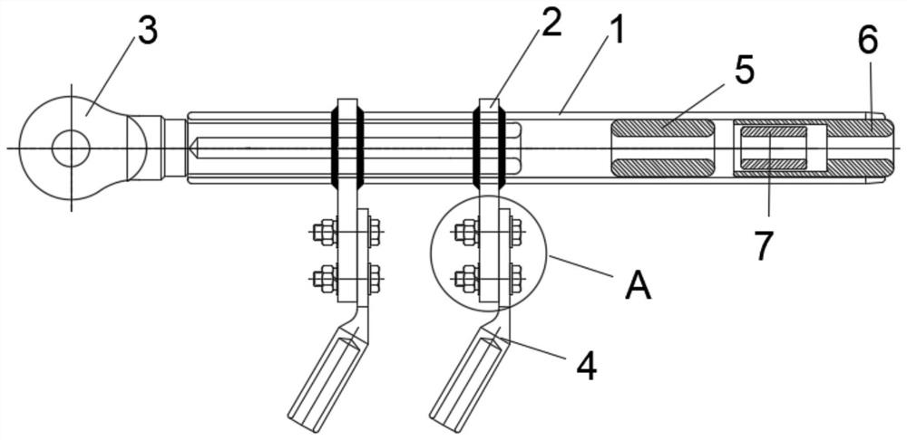
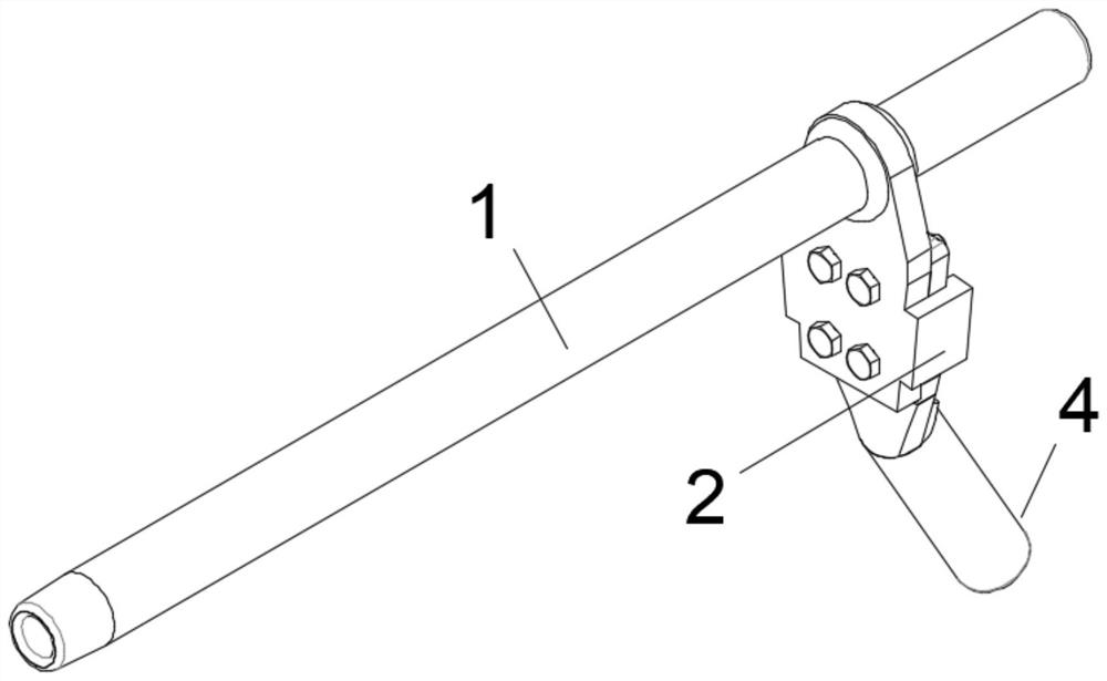
[0064] refer to Figure 6-9 , on the basis of the above-mentioned embodiment 1, a strain clamp includes a strain clamp described in embodiment 1, and also includes a drain plate 2 and a drain clamp 4, and the drain plate 2 is fixed to the On the main pipe 1, the drainage plate 2 and the drainage clamp 4 are provided with bolt holes 8, the drainage clamp 4 is connected with the drainage plate 2 through fastening bolts 9 and nuts 12, and the tightening Flat washers 10 are sleeved on both sides of the drain plate 2 and the drain clamp 4 on the fastening bolt 9 and the nut 12, and a spring washer is also sleeved on the fastening bolt 9 outside the flat washer 10 on the side close to the nut 12 11.

[0065] Preferably, the diversion plate 2 includes a first wedge-shaped plate 201, a C-shaped groove wall 202, and a socket hole 203. The upper side of the first wedge-shaped plate 201 is provided with a socket hole 203, and the socket hole 203 is fixed to the sleeve. Connected to the...

Embodiment 3

[0069] refer to Figure 10-12 , On the basis of the above-mentioned embodiment 2, a quick plug-in device 16 may also be provided in the drainage connection hole 403, and the quick-plug device 16 includes:

[0070] Push block 1601, first linkage 1602, pressure chamber 1603, movable chamber 1604, first spring 1605, first hinged rod 1606, second linkage 1607, second hinged rod 1608, balancer 1609, second spring 1610, Clamping warehouse 1611, first clamping block 1612, second clamping block 1613, synchronous gear 1614, connecting plate 1615, clamping shaft 1616, pressure piece 1617;

[0071] The outer wall of the pressure chamber 1603 is fixed to the drainage connection hole 403, the pressure chamber 1603 is a semi-closed structure, the inside of the pressure chamber 1603 is connected to one end of the first spring 1605, and the inner side of the pressure chamber 1603 is a movable chamber 1604, the first linkage 1602, the second linkage 1607, the first hinged rod 1606, and the se...


PUM


Abstract

The invention discloses a tension clamp, which comprises a tension clamp housing, a drainage plate, and a drainage clamp. The drainage plate is fixed on a main pipe, the drainage clamp and the drainage plate are connected by bolts, and a wedge-shaped groove is arranged on the drainage plate. , the wedge-shaped plate on the drainage clamp is sleeved in it, the tension clamp housing includes a main pipe and a steel anchor, the main pipe is a hollow structure, one end of the main pipe is fixedly connected with a steel anchor, and the other end of the main pipe is provided with a second A lined aluminum pipe, a second lined aluminum pipe, and reinforced steel pipe. The main tube of the hollow structure is equipped with the first lined aluminum tube, the second lined aluminum tube, and the reinforced steel tube to ensure the strength of the main tube and make it better adapt to harsh service conditions. The drainage plate is designed with wedge-shaped grooves. Used in conjunction with the wedge-shaped drainage clip, when the drainage clip moves down, the wedge-shaped structure makes the cooperation between the drainage plate and the drainage clip tighter and tighter, even when the fixing bolts are loose, the C-shaped groove makes it difficult for the drainage plate to come off.

Description

technical field [0001] The invention relates to the field of wire clips, in particular to a strain-resistant wire clip. Background technique [0002] With the rapid development of power application facilities in power distribution networks, in high-voltage and ultra-high-voltage overhead power systems, in order to anchor and tighten both ends of carbon fiber composite core conductors to poles or towers, strain clamps are required. The tension clamps connect the shell body (clamp shell) to the electric tower through a pull rod or a hanging plate, which requires considerable strength. Most of the main tubes of the existing clamp shells are single-layer main tubes, which are not very good. It can meet the harsh conditions of use of tension clamps. Contents of the invention [0003] The purpose of the present invention is to provide a tension clamp to solve the problems raised in the above-mentioned background technology. [0004] In order to achieve the above object, the pr...

Claims


Application Information

Patent Timeline
Patent Type & Authority Patents(China)
IPC IPC(8): H02G7/02H02G7/05H02G1/02G01D21/02
CPCH02G7/02H02G7/05H02G7/053H02G1/02G01D21/02
Inventor 周政敏朱砚刘艳明张勇侯艳森何文斌
Owner FOGANG XINYUAN HENGYE CABLE TECH CO LTD
Why Eureka
Try Eureka