Crop anti-rolling irrigation machine based on agricultural large-scale irrigation and use method thereof

A crop, a large-scale technology, applied in the field of agriculture, can solve the problems of adjusting the scope of irrigation, waste of resources, adjustment, etc., to avoid rolling to crops, preventing crops from rolling, and avoiding damage.

Inactive Publication Date: 2021-08-31
刁先梅
View PDF11 Cites 0 Cited by
  • Summary
  • Abstract
  • Description
  • Claims
  • Application Information

AI Technical Summary

Problems solved by technology

This method is the oldest and the most widely used and most important irrigation method. According to the different ways of moistening the soil, it can be divided into border irrigation, furrow irrigation, submerged irrigation and flood irrigation. Among them, promoting water tank mobile irrigation is also widely used. However, during the movement of the current mobile irrigation machine, since the distance between the two horizontal universal wheels cannot be adjusted according to the gap between the two rows of crops, the universal wheels roll on the crops and crush a large amount of water. crops, resulting in a waste of resources, and the current irrigator irrigation method is single, it is not convenient to adjust the scope of irrigation according to the area of ​​the crops, and the flow of water sprayed by the nozzle is not easy to control, and the practicability is lacking. Anti-rolling irrigation machine for range irrigation of crops and method of use thereof

Method used


Image

  • Crop anti-rolling irrigation machine based on agricultural large-scale irrigation and use method thereof
  • Crop anti-rolling irrigation machine based on agricultural large-scale irrigation and use method thereof
  • Crop anti-rolling irrigation machine based on agricultural large-scale irrigation and use method thereof

Examples


Embodiment 1

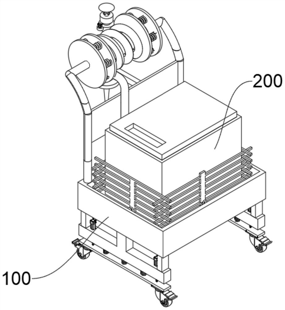
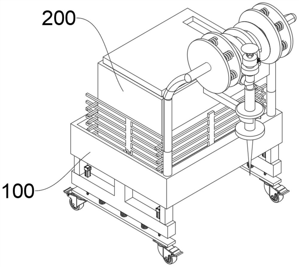
[0052] see Figure 1-Figure 6 As shown, this embodiment provides an anti-rolling irrigation machine for crops based on a wide range of agricultural irrigation, including at least:

[0053] Placement bucket 100, two symmetrical adjustment grooves 101 are provided at the bottom of the placement bucket 100, screw rods 102 are installed inside the adjustment grooves 101, the ends of the two screw rods 102 are fixedly connected with the first bevel gear 103, and the two second A second bevel gear 104 is meshed between the outer walls of a bevel gear 103, and the end of the second bevel gear 104 is connected with an output shaft of an adjustment motor 105, and the adjustment motor 105 is powered on to make it work. The output shaft drives the second bevel gear 104 to rotate, thereby meshing and driving the two first bevel gears 103 to rotate, so that the two screw rods 102 can rotate at the same time, and it is easier and more convenient inside the adjustment groove 101. There are t...

Embodiment 2

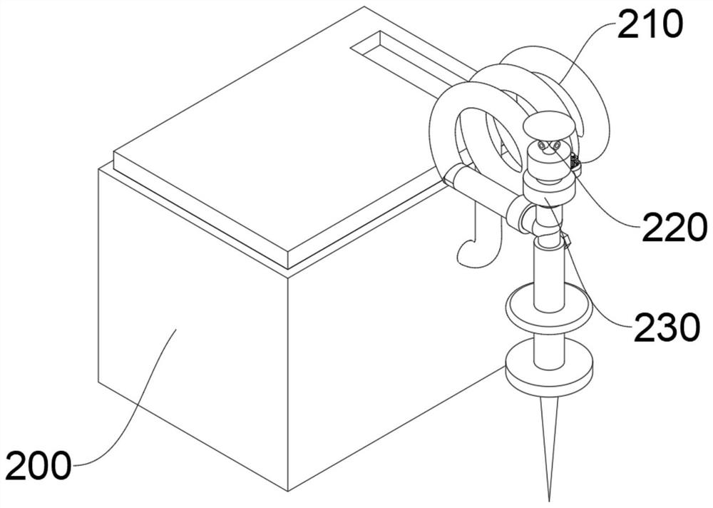
[0058] In order to wind the water pipe 210 around the outer wall of the finishing roller 121, avoid the water pipe 210 being dragged on the ground and be damaged, and avoid rolling the crops, the difference between this embodiment and the first embodiment is that, please refer to Figure 7 shown, where:

[0059] The edge of the placement bucket 100 is provided with a push rod 120, which can be held to push the placement bucket 100 to facilitate movement. The surface of the push rod 120 rotates with a finishing roller 121, and the two ends of the finishing roller 121 are fixedly connected to the limit plate 122, so that the water pipe can be moved. 210 is wound on the outer wall of the finishing roller 121, so that the water pipe 210 is spirally located between the two limiting plates 122, which can prevent the water pipe 210 from being dragged and damaged on the ground, and avoid rolling the crops, which is more practical.

[0060] It is worth noting that in order to limit and...

Embodiment 3

[0062] In order to clamp and limit the water tank 200 inside the placement bucket 100 and avoid falling during the movement, the difference between this embodiment and Embodiment 1 is that, please refer to Figure 8 shown, where:

[0063] Clamping plates 130 are provided on all four sides of the inner chamber of the placing bucket 100, and a fixed spring 131 is fixedly connected between the clamping plate 130 and the inner wall of the placing bucket 100, and the fixed spring 131 is compressed between the clamping plate 130 and the inner wall of the placing bucket 100. Put the water tank 200 inside the storage bucket 100, and the elastic force of the fixed spring 131 restores the clamping plate 130 to the water tank 200, and the clamping limit of the water tank 200 is inside the storage bucket 100, so as to avoid falling and pulling the clip during the movement. The holding plate 130 keeps the holding plate 130 away from the water tank 200, which facilitates subsequent removal ...


PUM


Abstract

The invention relates to the technical field of agriculture, in particular to a crop anti-rolling irrigation machine based on agricultural large-scale irrigation and a use method of the crop anti-rolling irrigation machine. thereof. The crop anti-rolling irrigation machine at least comprises a placing hopper and a water tank, two symmetrical adjusting grooves are formed in the bottom of the placing hopper, lead screws are rotatably arranged in the adjusting grooves, two symmetrical fixing plates are slidably arranged at the bottom of the placing hopper, adjusting plates are arranged at the centers of the tops of the fixing plates, the ends of the adjusting plates are in threaded connection with the outer walls of the lead screws, electric telescopic rods are embedded in the bottoms of the fixing plates, the ends of piston rods of the electric telescopic rods are fixedly connected with connecting plates, and universal wheels are arranged at the bottoms, close to the two ends, of the connecting plates. and the water tank is arranged at the top of the placing hopper, the bottom of an inner cavity of the water tank communicates with a water pipe through a water pump, and the end, extending out of the interior of the water tank, of the water pipe communicates with a spray head. The gaps between the universal wheels can be adjustedly conveniently according to the distance between crops, so that wheels of the universal wheels can move between two rows of crops, crop rolling can be avoided, and the irrigation flow can be adjusted.

Description

technical field [0001] The invention relates to the field of agricultural technology, in particular to an anti-rolling type irrigation machine for crops based on large-scale agricultural irrigation and a method for using the same. Background technique [0002] Agricultural irrigation methods can generally be divided into traditional surface irrigation, ordinary sprinkler irrigation and micro-irrigation. The traditional irrigation method water enters the field from the surface of the ground and infiltrates the soil by gravity and capillary action, so it is also called gravity irrigation. This method is the oldest and the most widely used and most important irrigation method. According to the different ways of moistening the soil, it can be divided into border irrigation, furrow irrigation, submerged irrigation and flood irrigation. Among them, promoting water tank mobile irrigation is also widely used. However, during the movement of the current mobile irrigation machine, sin...

Claims


Application Information

Patent Timeline
IPC IPC(8): A01G25/09
CPCA01G25/09
Inventor 刁先梅
Owner 刁先梅
Why Eureka
Try Eureka