
Swing-bucket-rotor for centrifugal machine

A centrifuge and leveling technology, which is applied to centrifuges and other directions, can solve the problems of unsuitable leveling rotors, etc., and achieve the effects of simple structure, reduced wind resistance, and reduced working energy consumption

Pending Publication Date: 2021-08-31
浙江灏东科技有限公司
View PDF2 Cites 2 Cited by
  • Summary
  • Abstract
  • Description
  • Claims
  • Application Information

AI Technical Summary

Problems solved by technology

Angle rotors with covers and swing-out rotors with windshield covers are obviously not suitable

Method used


Image

  • Swing-bucket-rotor for centrifugal machine
  • Swing-bucket-rotor for centrifugal machine
  • Swing-bucket-rotor for centrifugal machine

Examples


Embodiment Construction

[0036] The following will clearly and completely describe the technical solutions in the embodiments of the present invention with reference to the accompanying drawings in the embodiments of the present invention. Obviously, the described embodiments are only some, not all, embodiments of the present invention. Based on the embodiments of the present invention, all other embodiments obtained by persons of ordinary skill in the art without making creative efforts belong to the protection scope of the present invention.

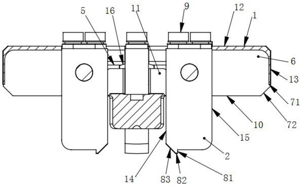
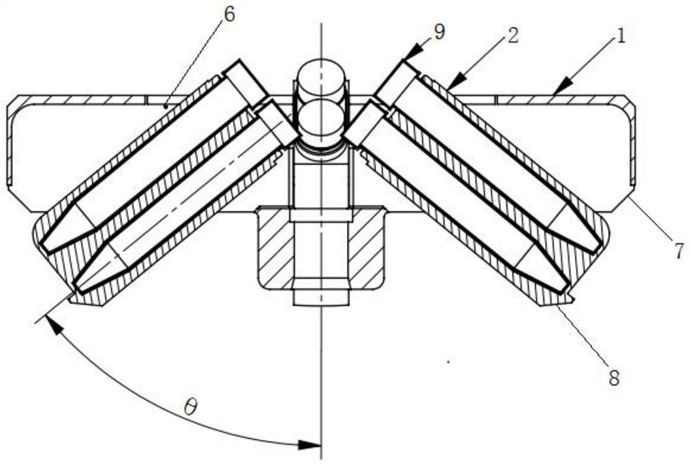
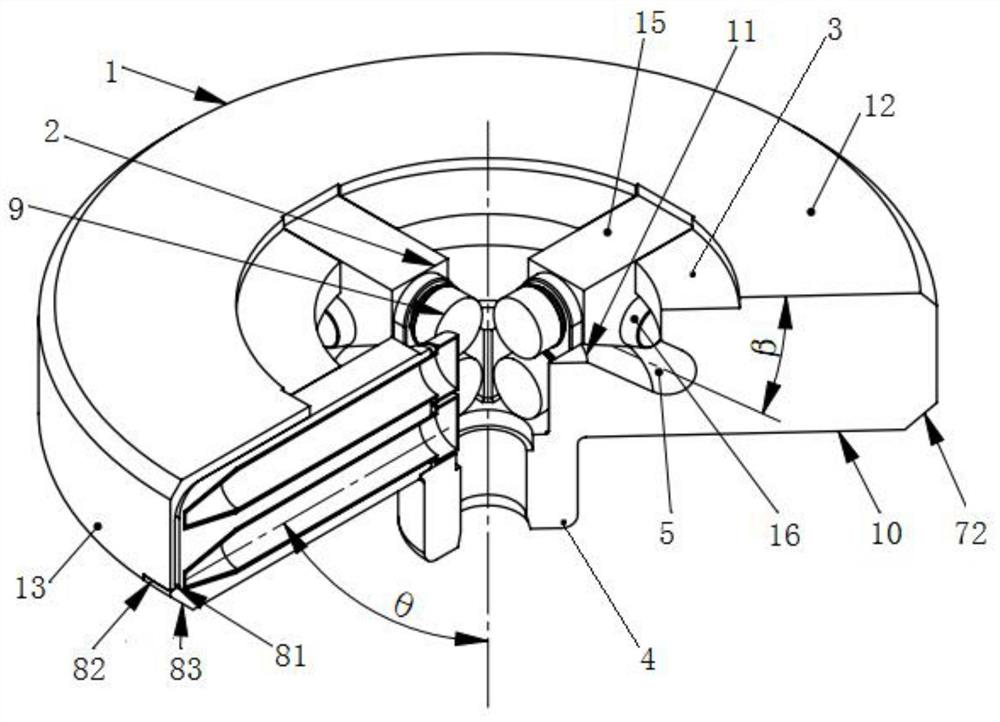
[0037] combined with Figure 1-3 , the embodiment of the present invention discloses a swinging rotor for a centrifuge, comprising a swinging rotor body 1 and a hanging basket 2 installed on the swinging rotor body 1; the swinging rotor body 1 is a hollow ring structure, and the swinging rotor body The inner upper end of 1 is provided with a hollow connecting ring 3, and the lower end of the swinging rotor body 1 is provided with a shaft sleeve 4, and the inne...


PUM


Abstract

The invention discloses a swing-bucket-rotor for a centrifugal machine. The swing-bucket-rotor comprises a swing-bucket-rotor body and a hanging basket installed on the swing-bucket-rotor body; the swing-bucket-rotor body is of a hollow annular structure, and a hollow connecting ring is arranged in an inner cavity of the swing-bucket-rotor body; an annular groove is formed in the hollow connecting ring, and the section of the annular groove is in an inclined U shape; a plurality of rectangular grooves are formed in the hollow connecting ring in the radial direction of the hollow connecting ring, the rectangular grooves are annularly arranged, the rectangular grooves communicate with the annular groove, and the rectangular grooves communicate with the inner cavity of the swing-bucket-rotor body; and cone-frustum-shaped protruding parts matched with the annular groove are arranged on the two sides of the opening end of the hanging basket, and the cone-frustum-shaped protruding parts on the two sides of the hanging basket are clamped in the annular groove and located at the bottom of the annular groove. During high-speed centrifugation, the hanging basket is automatically stored in the swing-bucket-rotor body, an approximately complete cake-shaped rotating body is synthesized, the wind resistance is small, the size is smaller than that of a conventional swing-bucket-rotor with the same centrifugal capacity, the wind resistance is greatly reduced, the working energy consumption of the centrifugal machine is reduced, and high-speed operation can be achieved.

Description

technical field [0001] The invention relates to the technical field of laboratory centrifuge devices, in particular to a swing-out rotor for a centrifuge. Background technique [0002] The centrifuge is provided with a rotor and a drive member for rotationally driving the rotor in a centrifuge chamber. The drive member rotates the rotor in the centrifuge chamber to exert centrifugal force, thereby centrifuging the sample in the sample container. The rotors used in centrifuges can be roughly divided into angle rotors and swing-flat rotors. In the case of an angle rotor, a number of sample containers filled with samples are accommodated in a storage hole, the storage hole is formed at a certain angle with respect to the drive shaft, and regardless of the magnitude of the centrifugal force, the storage hole and the drive shaft The relative angle of is always fixed. In addition, there are many cases where a rotor cover is installed in the opening on the upper part of the roto...

Claims


Application Information

Patent Timeline
Patent Type & Authority Applications(China)
IPC IPC(8): B04B5/04B04B7/00
CPCB04B5/0421B04B7/00
Inventor 文寄槐武育荣黎沐林魏强
Owner 浙江灏东科技有限公司
Features
  • Generate Ideas
  • Intellectual Property
  • Life Sciences
  • Materials
  • Tech Scout
  • Unparalleled Data Quality
  • Higher Quality Content
  • 60% Fewer Hallucinations
Learn More