
Spraying device for heat insulation layer of battery

A technology of spraying device and insulation layer, which is applied in the field of battery insulation layer spraying device, can solve the problems of high labor intensity, troublesome cleaning, easy spraying of foaming materials on the body, etc., and achieve the effect of reducing labor intensity and preventing falling and breaking

Active Publication Date: 2021-08-31
河南工学院
View PDF7 Cites 0 Cited by
  • Summary
  • Abstract
  • Description
  • Claims
  • Application Information

AI Technical Summary

Problems solved by technology

[0002] At present, various car companies have done a lot of research on active heating methods, but active heating is relatively complicated and costly, and not many are actually applied to products. In this case, the battery insulation layer has gradually entered people's field of vision. The thermal insulation layer of the material does not work consistently. If a high-efficiency thermal insulation material can be found, it will improve the current problem of limited low-temperature driving of electric vehicles to a certain extent, and lay the foundation for the further popularization of electric vehicles.
[0003] The foaming material is melted and evenly sprayed on the surface of the battery. During the spraying process, a large number of fine foams are formed inside the material. After solidification, it has the functions of cushioning, sound absorption, vibration absorption, heat preservation, and filtration. Currently, the melted foaming material is sprayed on the surface of the battery. It is generally carried out manually with a hand-held spray gun. When spraying, it is necessary to hold the spray gun to move the spray gun repeatedly along the battery. The arm is prone to soreness and labor intensity after holding the spray gun for a long time. The final foaming material is easy to spray on the body, and it is more troublesome to clean

Method used


Image

  • Spraying device for heat insulation layer of battery
  • Spraying device for heat insulation layer of battery
  • Spraying device for heat insulation layer of battery

Examples


Embodiment Construction

[0038]In order to facilitate the understanding of the present invention, the present invention will be described more fully below with reference to the associated drawings. Preferred embodiments of the invention are shown in the accompanying drawings. However, the present invention can be embodied in many different forms and is not limited to the embodiments described herein. On the contrary, the purpose of providing these embodiments is to make the disclosure of the present invention more thorough and comprehensive.

[0039] It should be noted that when an element is referred to as being “fixed” to another element, it can be directly on the other element or there can also be an intervening element. When an element is referred to as being "connected to" another element, it can be directly connected to the other element or intervening elements may also be present. The terms "inner", "outer", "left", "right" and similar expressions are used herein for the purpose of descriptio...


PUM


Abstract

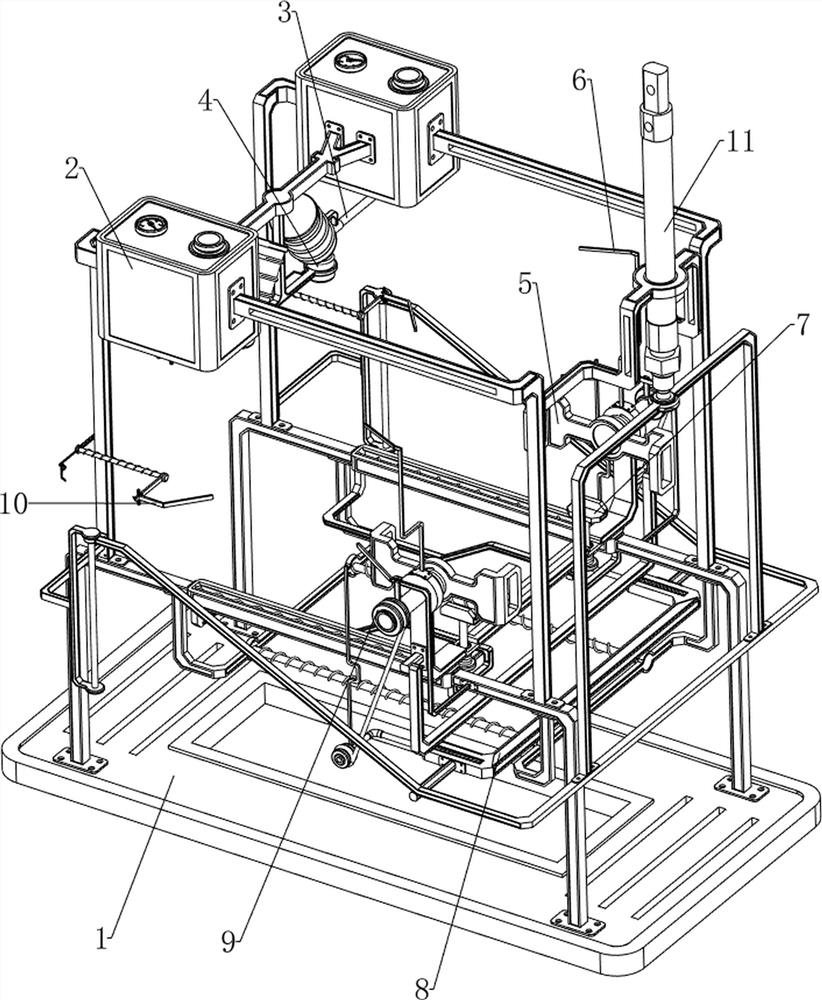
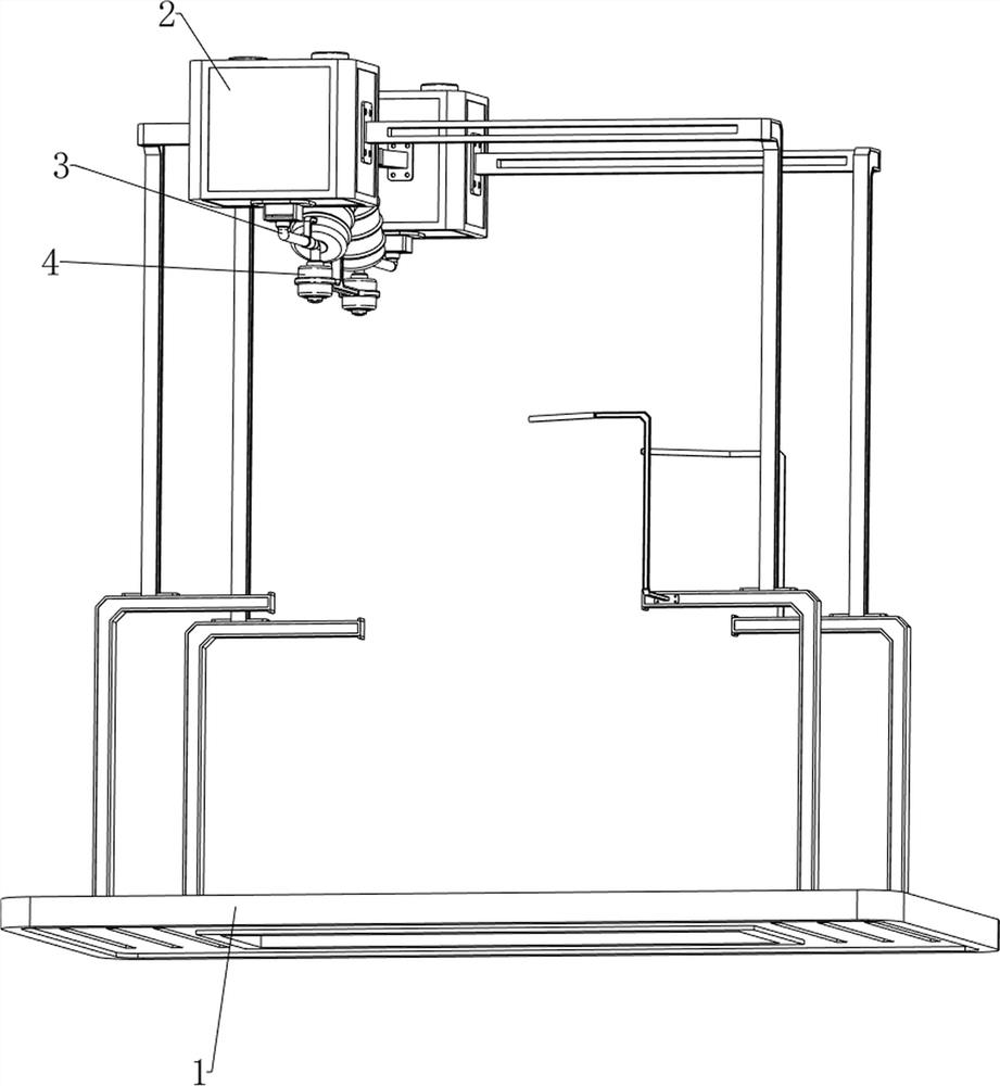
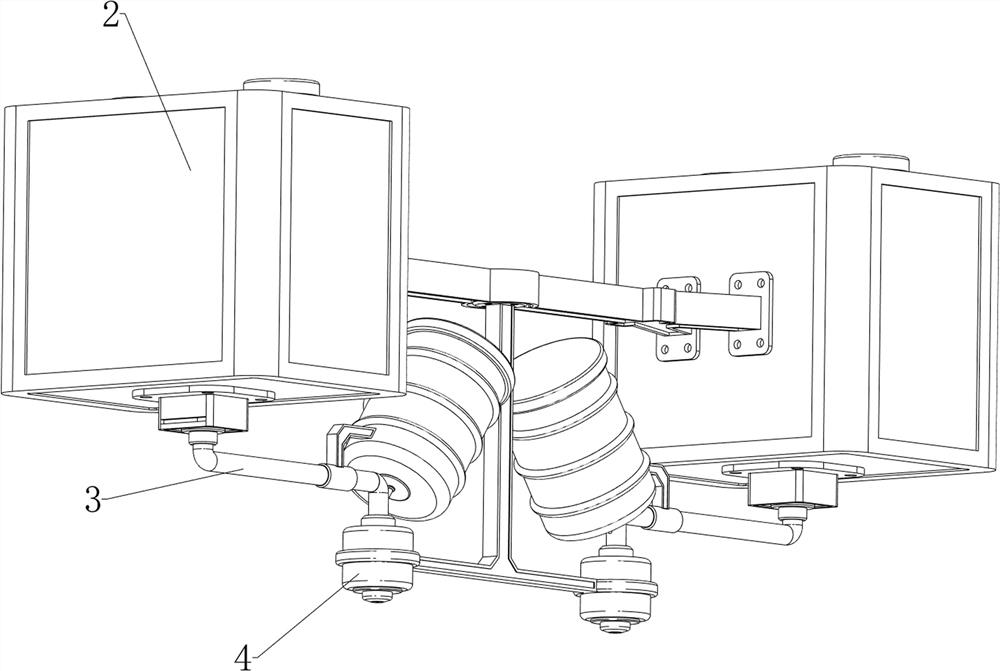
The invention relates to a spraying device for a heat insulation layer of a battery. The spraying device for the heat insulation layer of the battery comprises a supporting frame, air pressure boxes, an air pipe, a spraying head, a clamping mechanism and deflation mechanisms, wherein the upper portion of the left side of the supporting frame is connected with the two air pressure boxes, the air pressure boxes are used for pressurizing the spraying head, the bottoms of the air pressure boxes are connected with the air pipe, the air pipe is used for conveying air pressure, and the upper portion of the air pipe is connected with a storage barrel; the storage barrel communicates with the air pipe and is used for storing a spraying material, a cover is connected to the top of the storage barrel in a clamped mode, the bottom end of the air pipe is connected with the spraying head, the spraying head is used for spraying the spraying material to the surface of the battery, the clamping mechanism is arranged on the supporting frame and used for clamping the battery, and the deflation mechanisms are arranged on the air pressure boxes; and the deflation mechanisms are used for controlling conveying for the air pressure in the air pressure boxes. The clamping mechanism can clamp the battery, and the air pressure boxes and the deflation mechanisms are matched to pressurize the spraying head, so that the spraying head sprays the molten foaming material to the surface of the battery.

Description

technical field [0001] The invention relates to a spray coating device, in particular to a battery insulation layer spray coating device. Background technique [0002] At present, various car companies have done a lot of research on active heating methods, but active heating is relatively complicated and costly, and not many are actually applied to products. In this case, the battery insulation layer has gradually entered people's field of vision. The thermal insulation layer of the material does not work consistently. If an efficient thermal insulation material can be found, it will improve the current limited low-temperature driving problem of electric vehicles to a certain extent, and lay the foundation for the further popularization of electric vehicles. [0003] The foaming material is melted and evenly sprayed on the surface of the battery. During the spraying process, a large number of fine foams are formed inside the material. After solidification, it has the functio...

Claims


Application Information

Patent Timeline
IPC IPC(8): B05B9/04B05B13/02
CPCB05B9/04B05B13/0221B05B13/0228B05B13/0285
Inventor 王强胜孔春辉徐文博李建雄宋娟
Owner 河南工学院
Learn More