
Glue mixing head for numerical control sealing dispenser

A dispensing machine and glue mixing technology, which is applied in the direction of spraying devices, coatings, and devices for coating liquid on the surface, etc. It can solve the problems of insensitivity to opening and closing delays of sealing valves, affecting sealing effects, and unsmooth glue discharge. , to achieve the effect of high-pressure water washing thoroughly, reliable and reasonable sensitivity, and reasonable and compact structure

Pending Publication Date: 2021-08-31
洛阳市锐创电气设备有限公司
View PDF0 Cites 0 Cited by
  • Summary
  • Abstract
  • Description
  • Claims
  • Application Information

AI Technical Summary

Problems solved by technology

[0003] At present, due to the structural design of the existing CNC sealing dispensing machine mixing head in China, there are the following problems: 1. The mixing head A glue valve, B glue valve, flushing valve, water circulation, glue mixing chamber, and water circulation constant temperature of the glue dispensing machine The system is a split structure. After installation, the mixing head is too large, with many parts and complex structure, which is extremely inconvenient for maintenance; 2. The mixing head is easy to drip glue, and the opening and closing delay of the sealing valve is not sensitive, which may easily cause dispensing The combination of the starting point and the end point of the rubber strip will affect the sealing effect; 3. Due to the structural design of the mixing head in the dispensing head, the glue will not flow smoothly, which will easily cause the glue to be excessively stirred in the glue mixing chamber and cause scorching; 4. , Sometimes it is necessary to design two different specifications of the glue head, the constant glue head and the micro glue head, according to the width of the product glue strip, the versatility is relatively poor

Method used


Image

  • Glue mixing head for numerical control sealing dispenser
  • Glue mixing head for numerical control sealing dispenser
  • Glue mixing head for numerical control sealing dispenser

Examples


specific Embodiment 1

[0035] Specific embodiment 1: The technical solution of the present invention will be clearly and completely described below in conjunction with the embodiments. Obviously, the described embodiments are part of the embodiments of the present invention, but not all of them. Based on the embodiments of the present invention, all other embodiments obtained by persons of ordinary skill in the art without making creative efforts belong to the protection scope of the present invention. It should be noted that in the present invention, unless otherwise specified, all the implementation modes and preferred implementation methods mentioned herein can be combined with each other to form a new technical solution. In the present invention, if there is no special description, all the technical features and preferred features mentioned herein can be combined with each other to form a new technical solution. The "ranges" disclosed herein may be in the form of lower limits and upper limits, a...


PUM


Abstract

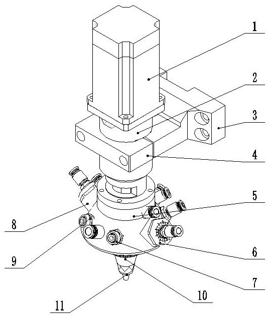
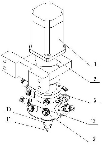
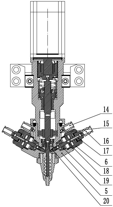
The invention relates to the field of dispensing heads for numerical control dispensing machine equipment, in particular to a glue mixing head for a numerical control sealing dispensing machine. The glue mixing head comprises: a servo motor, a motor mounting base, a motor fixing base, a motor fixing base hoop, a channel chamber, an A glue valve assembly, a B glue valve assembly, a flushing valve assembly I, a flushing valve assembly II, a water circulation constant temperature assembly, a shaft driving glue sealing assembly and a mixed glue discharging assembly. The motor mounting base is disposed in a front groove formed by combining the motor mounting base and the motor fixing base and is fixedly connected and mounted by connecting bolts. The butterfly design structure is adopted, the A glue valve assembly, the B glue valve assembly, the flushing valve assembly I and the flushing valve assembly II are designed to form the 60-degree included angle, glue discharging of the glue dispensing head can be smoother, high-pressure water is used for washing cleanly and thoroughly, a stirring head is high in stirring efficiency, and a mixed glue body completely protrudes out of the channel chamber, so that glue dispensing can be performed under the condition that a glue outlet nozzle is shortest, and glue outlet is smoother.

Description

technical field [0001] The invention relates to the field of glue dispensing heads for numerically controlled glue dispensing machines, in particular to a glue mixing head for numerically controlled sealing glue dispensing machines. Background technique [0002] Dispensing machine, also known as gluing machine, gluing machine, etc., is mainly suitable for processing processes such as polymerization sealing, gluing and pouring of easy-flowing or viscous liquid glue. Dispensing machines generally use three-axis or multi-axis Axis linkage, can be used for plane gluing (such as square, round and various special-shaped graphics), can also be used for three-dimensional gluing, precise positioning, precise control of glue, with the characteristics of no glue leakage, no glue dripping, glue dispenser The application of the product has greatly improved the production efficiency of the product and improved the product quality. In terms of automation, it can realize three-axis linkage,...

Claims


Application Information

Patent Timeline
IPC IPC(8): B05C5/02B05C11/10B05B15/55
CPCB05C5/02B05C11/1026B05C11/1036B05B15/55
Inventor 付强樊英国
Owner 洛阳市锐创电气设备有限公司
Learn More