
Constraint system and method for rolling forming of metal laminated composite plate

A restraint system and clad plate technology are applied in the field of restraint systems for rolling and forming of metal layered clad plates, which can solve the problems of less types and sizes of billet metals, fluctuation of interface bonding quality, fluctuation of interface compound quality, etc. Low, improve the service life, prolong the service life effect

Active Publication Date: 2022-04-15
UNIV OF SCI & TECH BEIJING
View PDF10 Cites 0 Cited by
  • Summary
  • Abstract
  • Description
  • Claims
  • Application Information

AI Technical Summary

Problems solved by technology

[0006] Aiming at the problems of sheet shape defects, interface composite quality fluctuations, and less types and sizes of billet metals that exist in the preparation of metal layered composite sheets by the current cold-hot rolling composite method
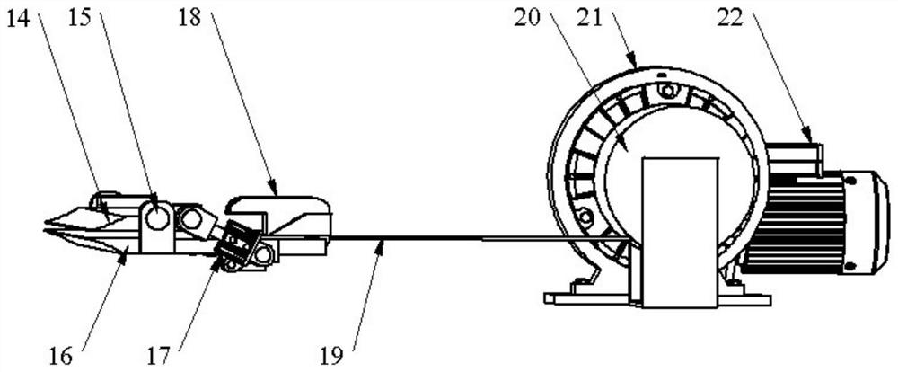
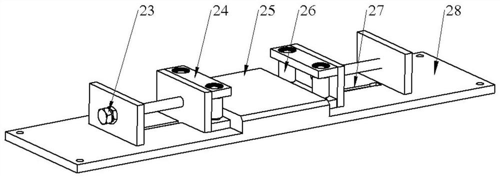
The present invention proposes to install restraint devices or restraint-tension devices respectively at the entrance and exit of the cold rolling mill and the hot rolling mill. Problems such as side bending, misalignment, lateral offset, bending, uneven thickness, warpage and the resulting fluctuations in the interface bonding quality that exist in the process of rolling and forming metal laminated composite plates can obtain high-quality metal with good plate shape laminated composite panel
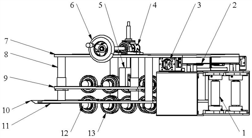
The entrance restraint device of the cold rolling mill is used to exert restraint force on the width direction and the thickness direction of the metal laminated slab, and solve the side bending of the metal laminated slab or the cold-rolled pre-composite plate, the misalignment of the cladding layer and the base layer, and the lateral deflection during the cold rolling process. Move and other issues

Method used


Image

  • Constraint system and method for rolling forming of metal laminated composite plate
  • Constraint system and method for rolling forming of metal laminated composite plate
  • Constraint system and method for rolling forming of metal laminated composite plate

Examples


Embodiment 1

[0042] Cold-hot rolling compound forming TA1 titanium / Q235 steel layered composite plate.

[0043]The thickness of the clad TA1 titanium plate is 1 mm and the width is 400 mm, and the thickness of the base Q235 steel plate is 5 mm and the width is 400 mm. The TA1 titanium plate and the Q235 steel plate to be compounded surface treated are assembled into billets, and then the steel side of the TA1 titanium / Q235 steel laminated slab is placed between the pressure plate 9 and the bottom plate 11 of the entrance restraint device of the cold rolling mill. Then, the linear module 3 controls the rotation of the lead screw 2 to control the horizontal movement of the two groups of clamping shafts 1, and adjusts the horizontal distance of the two groups of clamping shafts 1 to limit the horizontal position of the TA1 titanium / Q235 steel laminated slab. Then rotate the hand wheel 6 to control the elevator 4, and the elevator 4 drives the lifting seat 5 and the pressure plate 9 to move ve...

Embodiment 2

[0045] Cold-hot rolling compound forming 3003 / 6061 aluminum alloy layered composite plate.

[0046] The thickness of the clad 3003 aluminum plate is 3mm and the width is 350mm, and the thickness of the base 6061 aluminum plate is 6mm and the width is 350mm. The 3003 aluminum plate and the 6061 aluminum plate are assembled after surface treatment, and then the 6061 aluminum face of the 3003 / 6061 aluminum alloy laminated slab is placed between the pressure plate 9 and the bottom plate 11 of the entrance restraint device of the cold rolling mill. Then, the linear module 3 controls the rotation of the lead screw 2 to control the horizontal movement of the two groups of clamping shafts 1, and adjusts the horizontal distance of the two groups of clamping shafts 1 to limit the horizontal position of the 3003 / 6061 aluminum alloy laminated slab. Rotate the hand wheel 6 to control the lifter 4 to drive the lifting seat 5 and the pressing plate 9 to move vertically together, so that the ...

Embodiment 3

[0048] Cold-hot rolling compound forming 3003 / 6061 / 3003 aluminum alloy laminated composite plate.

[0049] The thickness of the composite 3003 aluminum plate is 2mm and the width is 350mm, and the thickness of the base 6061 aluminum plate is 5mm and the width is 350mm. After the surface treatment of the 3003 aluminum plate and the 6061 aluminum plate to be compounded, the blanks are stacked in the order of 3003 / 6061 / 3003, and then the 3003 / 6061 / 3003 aluminum alloy laminated slab is placed into the pressure plate 9 of the entrance restraint device of the cold rolling mill and Between the bottom plate 11. Then the linear module 3 controls the rotation of the lead screw 2 to control the horizontal and horizontal movement of the two groups of clamping shafts 1, and adjust the horizontal distance of the two groups of clamping shafts 1 to make it the same width as the 3003 / 6061 / 3003 aluminum alloy laminated slab, horizontal Limit 3003 / 6061 / 3003 aluminum alloy laminated slabs. Then...


PUM

PropertyMeasurementUnit
thicknessaaaaaaaaaa
widthaaaaaaaaaa
thicknessaaaaaaaaaa

Abstract

The invention discloses a rolling forming constraining system and method of a metal layered composite plate, which belongs to the technical field of metal layered composite plate rolling. The restraint device consists of a cold rolling mill entrance restraint device, a cold rolling mill exit restraint-tension device, a hot rolling mill entrance restraint device and a hot rolling mill exit restraint device. The invention can effectively improve problems such as side bending, misalignment, lateral offset, bending, uneven thickness and warping of the metal layered composite plate in the process of cold-hot rolling composite forming, reduce rolling force, and reduce rolling mill load , to ensure a smooth forming process, to obtain a metal layered composite plate with high interface bonding quality and good plate shape, and the device structure is simple, the method is flexible in operation, and has a wide range of applications.

Description

technical field [0001] The invention belongs to the technical field of metal layered composite plate rolling, and in particular relates to a rolling forming constraining system and method of a metal layered composite plate. Background technique [0002] When using the cold-hot rolling compound method to prepare metal layered composite plates, firstly, the surfaces to be compounded of two or more metal slabs are subjected to surface treatment such as mechanical grinding, and then the metal slabs are stacked to form blanks, and then The metal laminated slab is cold-rolled and pre-compounded at room temperature, and finally the cold-rolled pre-compounded plate is heated and then hot-rolled and composited to obtain a metal layered composite plate. During cold-rolled pre-composite forming, due to the different deformation resistance of different metals, the cold-rolled pre-composite plate will bend towards the metal layer with greater deformation resistance during the forming pro...

Claims


Application Information

Patent Timeline
Patent Type & Authority Patents(China)
IPC IPC(8): B21B37/16B21B37/48B21B37/58B21B39/02
CPCB21B37/16B21B37/48B21B37/58B21B39/02
Inventor 刘雪峰白于良
Owner UNIV OF SCI & TECH BEIJING
Learn More