Printer nozzle motion adjusting device

A motion adjustment and printer technology, applied in printing devices, power transmission devices, printing, etc., can solve the problems of X-axis transmission devices occupying a large area, difficult to ensure adjustment accuracy, and affecting the stability of printing carriages

Active Publication Date: 2021-08-31
BEIJING ZHONGDIAN YUANDE TECH CO LTD
View PDF9 Cites 0 Cited by
  • Summary
  • Abstract
  • Description
  • Claims
  • Application Information

AI Technical Summary

Problems solved by technology

[0008] 1) The size of the cantilever beam of the cantilever beam type X-axis transmission device affects the size of the entire X-axis transmission device, making the X-axis transmission device occupy a large area, and it is difficult to control the motion stability of the printing carriage;
[0009] 2) When the printing car is moving up and down, the manual adjustment method increases labor costs, and it is easy to misuse, and the adjustment accuracy is difficult to guarantee; in the automatic adjustment mode, the lifting load of the printing car is too large, and the lifting accuracy is difficult to control, and a high-power motor is used While controlling the movement, it will also increa...

Method used


Image

  • Printer nozzle motion adjusting device
  • Printer nozzle motion adjusting device
  • Printer nozzle motion adjusting device

Examples


Embodiment 1

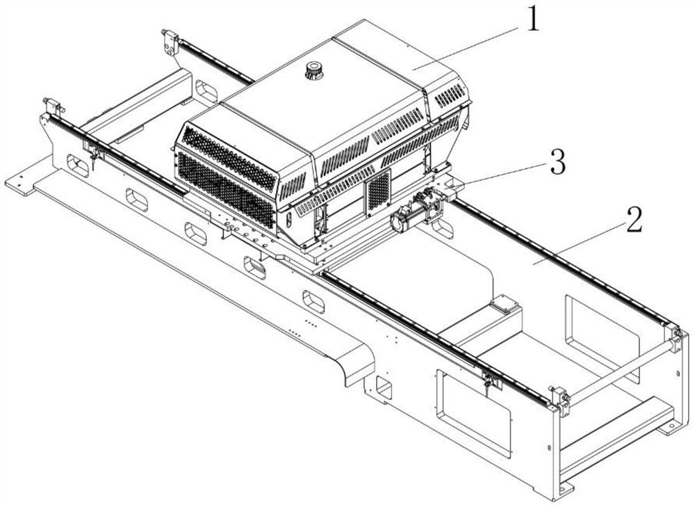
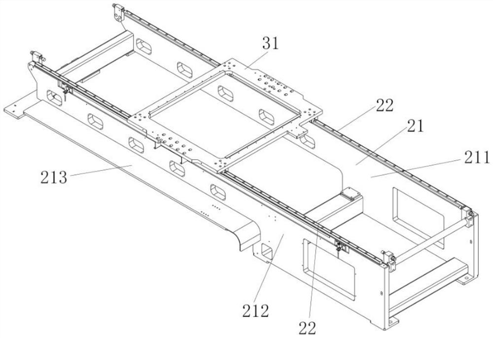
[0049] refer to figure 1 and figure 2 As shown, a printer nozzle movement adjustment device, the improvement of which is that it includes a printing cart 1, a Y-axis transmission device 3 that carries the printing cart 1 and drives the printing cart 1 to move along the Y axis, carries the printing cart 1 and the The Y-axis transmission device 3 and the X-axis transmission device 2 that drives the printing cart 1 and the Y-axis transmission device 3 to move along the X-axis; the X-axis transmission device 2 includes the printing cart 1 and the Y-axis transmission device 3 The main frame 21, the first control device 24 for controlling the movement and movement position of the printing carriage 1 and the Y-axis transmission device 3, the first guide installed above the main frame 21 and guiding the movement of the printing carriage 1 device; the main frame 21 includes a first side plate 211 and a second side plate 212 on both sides and a support beam between the first side plat...

Embodiment 2

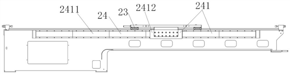
[0056] On the basis of embodiment 1, with reference to image 3 As shown, the first control device 24 includes a linear motor 241 for driving the Y-axis transmission device 3 to move, and a position detection device 242 for detecting the moving position of the Y-axis transmission device 3 .

[0057] Further, the linear motor 241 includes a linear motor stator 2411 mounted on the side of the first side plate 211 or the second side plate 212, mounted on one side of the Y-axis transmission device 3 and connected to the linear motor stator 2411 a linear motor mover 2412 that cooperates with each other; the position detection device 242 includes a magnetic grid 2421 installed on the side of the first side plate 211 or the second side plate 212, a magnetic grid installed on the Y-axis transmission device 3 Grid read head 2422.

[0058] In this embodiment, the linear motor 241 has the advantages of simple structure, high positioning accuracy, fast response, high sensitivity, good fo...

Embodiment 3

[0060] On the basis of embodiment 2, with reference to Figure 4 As shown, the first control device 24 includes a safety travel control device 243 for defining the start position and end position of the travel of the Y-axis transmission device 3, which is arranged on the first side plate 211 or the second side plate The anti-collision device 244 at the limit position of the Y-axis transmission device 3 on the 212; the safety travel control device 243 includes a position sensor 2431, and a sensor stopper matching the position sensor 2431 is installed on the Y-axis transmission device 3 Sheet II 2432 ; the anti-collision device 244 includes an anti-collision block 2441 and a buffer member 2442 mounted on the anti-collision block 2441 and facing the Y-axis transmission device 3 .

[0061] In this embodiment, when the sensor block II2432 reaches the position of the position sensor 2431, the sensor will transmit a signal to the linear motor 241, thereby stopping the movement of the...


PUM


Abstract

The invention relates to a printer nozzle motion adjusting device. The device comprises a printing trolley, a Y-axis transmission device and an X-axis transmission device, wherein the Y-axis transmission device bears the printing trolley and drives the printing trolley to move along a Y-axis, and the X-axis transmission device bears the printing trolley and the Y-axis transmission device and drives the printing trolley and the Y-axis transmission device to move along an X-axis; the X-axis transmission device comprises a main frame used for bearing the printing trolley and the Y-axis transmission device, a first control device used for controlling movement and movement positions of the printing trolley and the Y-axis transmission device, and a first guide device installed above the main frame and used for guiding movement of the printing trolley; the main frame comprises a first side plate and a second side plate which are located on the two sides, and a supporting beam located between the first side plate and the second side plate; the Y-axis transmission device is erected above the first side plate and the second side plate; and the printing trolley is erected in the Y-axis transmission device and located between the first side plate and the second side plate. The device has the beneficial effects of compact structure, high control precision, high printing efficiency and the like.

Description

technical field [0001] The invention relates to the technical field of inkjet printing, in particular to a motion adjustment device for a nozzle of a printer. Background technique [0002] The X-axis is the horizontal scanning direction of the printing carriage of the inkjet printer, and the Y-axis is the longitudinal stepping direction of the printing carriage. The X-axis transmission device of the printing carriage of the inkjet printing equipment in the prior art generally adopts a cantilever structure. Scan back and forth on the beam to eject ink droplets onto the printing medium to print images or text. As disclosed in Chinese patent CN111376615A, a cantilever beam structure printing cart includes a nozzle base plate, a sub-ink fixing bracket, a negative pressure system mounting bracket and a circuit board mounting plate, and the circuit board mounting plate is a rear circuit board mounting plate. Installed on the rear end of the sprinkler trolley, it is used to fix th...

Claims


Application Information

Patent Timeline
IPC IPC(8): B41J25/00B41J23/00B41J29/393
CPCB41J25/001B41J23/00B41J29/393
Inventor 单健王家远闫峂
Owner BEIJING ZHONGDIAN YUANDE TECH CO LTD
Why Eureka
Try Eureka