
Anti-deformation mold pressing device for disc spring tempering

An anti-deformation, disc spring technology, applied in the field of disc spring processing, can solve the problems of small scope of application, insufficient versatility, and inability to adjust the inclination angle according to needs, so as to achieve the effect of improving versatility and convenient adjustment.

Active Publication Date: 2021-08-31
浙江高强度紧固件有限公司
View PDF4 Cites 0 Cited by
  • Summary
  • Abstract
  • Description
  • Claims
  • Application Information

AI Technical Summary

Problems solved by technology

[0003]At present, the disc spring is often set on the conical support structure during the tempering process of the disc spring, but the shape of the conical support structure used to support the disc spring is fixed and inclined. The angle cannot be adjusted according to the needs, it is only suitable for disc springs with a single slope, the scope of application is small, and the versatility is insufficient

Method used


Image

  • Anti-deformation mold pressing device for disc spring tempering
  • Anti-deformation mold pressing device for disc spring tempering
  • Anti-deformation mold pressing device for disc spring tempering

Examples


Embodiment 1

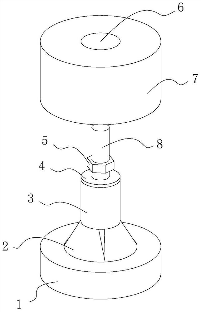
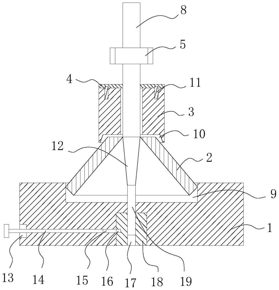
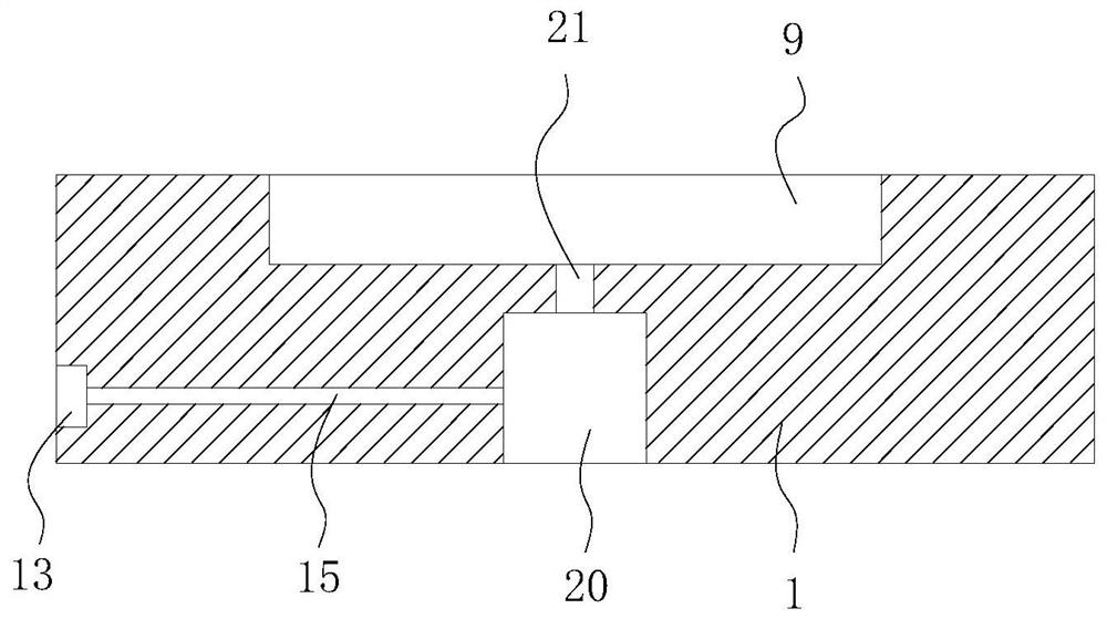
[0027] Example 1: See Figure 1 to Figure 5 , the present invention provides a technical solution: a disc spring tempering anti-deformation molding device, including a base 1, a groove 9 is opened in the middle of the upper surface of the base 1, and a number of narrow upper and lower wide grooves are arranged in the groove 9. The arc-shaped block 2 used to support the disc spring, one end of the arc-shaped block 2 in the groove 9 is hingedly connected with the base 1, the groove 9 is a circular structure, and the groove 9 provides installation space for the lower end of the arc-shaped block 2, Simultaneously play the effect of limiting the position of the lower end of the arc block 2 .

[0028] A tapered column 12 with a wide top and a narrow bottom for supporting the upper end of the arc-shaped block 2 is provided between several arc-shaped blocks 2. The lower end of the tapered column 12 is fixedly connected with a second stud 19, and the second stud 19 is connected to the ...

Embodiment 2

[0036] Example 2: see Figure 6 , a tapered sleeve 27 with a wide top and a narrow bottom for supporting the upper end of the arc-shaped block 2 is provided between several arc-shaped blocks 2, the tapered sleeve 27 is internally threaded with a threaded rod 28, and the lower end of the threaded rod 28 is threaded with the base 1 , when the tapered sleeve 27 is worn, the tapered sleeve 27 is removed from the threaded rod 28 and replaced.


PUM


Abstract

The invention provides an anti-deformation mold pressing device for disc spring tempering. The anti-deformation mold pressing device comprises a base, a groove is formed in the middle of the upper surface of the base, a plurality of arc-shaped blocks which are narrow in top and wide in bottom and are used for supporting disc springs are arranged in the groove, the ends, located in the groove, of the arc-shaped blocks are connected with the base in a hinged mode, conical columns which are wide in top and narrow in bottom and are used for supporting the upper ends of the arc-shaped blocks are arranged among the multiple arc-shaped blocks, a second stud is fixedly connected to the lower ends of the conical columns and is in threaded connection with the base, a first stud is fixedly connected to the upper ends of the conical columns, a cylinder used for pressing and holding the arc-shaped blocks is arranged on the first stud in a sleeving mode, the lower surface of the cylinder is provided with conical grooves which are narrow in top and wide in bottom, the first stud is in threaded connection with a nut, and the nut is arranged on the side, deviating from the arc-shaped blocks, of the cylinder. Compared with the prior art, the anti-deformation mold pressing device for the disc spring tempering has the following beneficial effects that the inclination angle of the arc-shaped blocks can be conveniently adjusted, the device can be conveniently matched with the disc springs with different inclinations, and the universality is improved.

Description

technical field [0001] The invention relates to an anti-deformation molding device for disc spring tempering, which belongs to the technical field of disc spring processing. Background technique [0002] Disc springs are also known as Belleville spring washers. The shape of the disc spring is a conical disc, which is different from the traditional spring, and has its special function. The main features are large load, short stroke, small space required, convenient combination and use, easy maintenance and replacement, economical and safe high. It is suitable for precision heavy machinery with small space and heavy load. The optimal range of its compression stroke is between 10% and 75% of its maximum compression stroke. [0003] At present, the disc spring is often set on the conical support structure during the tempering process of the disc spring, but the shape of the conical support structure used to support the disc spring is fixed, and the inclination angle cannot be...

Claims


Application Information

Patent Timeline
Patent Type & Authority Applications(China)
IPC IPC(8): C21D9/02
CPCC21D9/02
Inventor 葛少辉戴建海张鑫伟李兴标
Owner 浙江高强度紧固件有限公司
Learn More