
A Discrimination Method for Fault Sections in Hub Areas Based on Power Flow Analysis

A technology of fault section and power flow analysis, applied in fault location, fault detection according to conductor type, information technology support system, etc., can solve the problems of complex fault section judgment, difficult to cooperate with feeder action level difference, skipping trip, etc. The effect of intelligent fault discrimination level, improved transportation adaptability, and improved transportation quality

Active Publication Date: 2021-10-29
CHINA RAILWAYS CORPORATION +1
View PDF14 Cites 0 Cited by
  • Summary
  • Abstract
  • Description
  • Claims
  • Application Information

AI Technical Summary

Problems solved by technology

[0002] At present, the hub area in our country adopts the power supply scheme of switching stations for the flexibility of splitting power supply in different fields. Large-scale hubs have a power supply scheme in which switching stations are connected to switching stations. In the case of tripping, in addition, there are many stages of switching stations in the hub area. After multi-stage conduction, the voltage difference between the two ends of the electric segment is large. The switch at the section will enable the catenary in the hub area to realize the ring network power supply network, the judgment of the fault section becomes more complicated, and the quick recovery time after the fault becomes longer. In order to improve the efficiency of fault finding, it is urgent to provide a new fault section discrimination method

Method used


Image

  • A Discrimination Method for Fault Sections in Hub Areas Based on Power Flow Analysis
  • A Discrimination Method for Fault Sections in Hub Areas Based on Power Flow Analysis
  • A Discrimination Method for Fault Sections in Hub Areas Based on Power Flow Analysis

Examples


Embodiment 1

[0047] Embodiment 1: The implementation process of the present invention based on the power flow analysis method for the fault section in the hub area

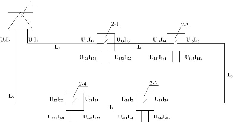
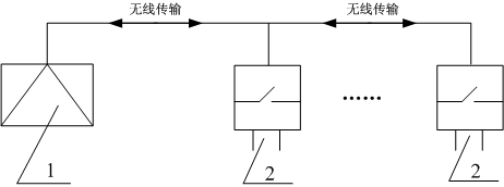
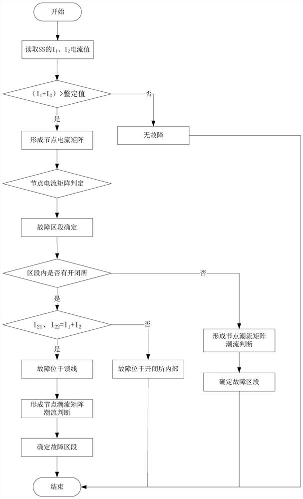
[0048] Such as figure 1 and image 3 As shown, the outgoing current I of the traction substation 1 feeder 1 and I 2 , divide the fault section according to the distribution of switching stations, and divide L between the first switching station 2-1 and traction substation 1 1 , forming two node currents I 1 and I 12 , node voltage U 1 and U 12 ; The feeder current and voltage of the first switching station 2-1 are: I 121 , U 121 and I 122 , U 122 By analogy, the current and voltage of each section can be established, figure 1 L is formed in 1 , L 2 , L 3 , L 4 , L 5 5 sections, the first switching station 2-1, the second switching station 2-2, the third switching station 2-4, and the fourth switching station 2-3 are respectively feeder sections, and no loop is formed on one side segment of the net.

[0049]...


PUM


Abstract

The invention discloses a method and device for discriminating a fault section in a hub area based on power flow analysis, which includes a power supply module connected to an internal connection module, a CPU module and a wireless communication module; obtains voltage and current data at the feeder line of a traction substation; Transmission obtains the current and voltage data of the incoming and outgoing lines of multiple switching stations and the current and voltage data of the switching station feeders; establishes the current and voltage data of each section; judges the section where the short-circuit fault occurs through the current relationship between nodes. The beneficial effect is that the short-circuit fault section can be quickly judged through the node current and the node power matrix, and the fault section can be quickly isolated, which solves the difficulty in judging the fault section of the ring network power supply in the hub area and the leapfrog tripping of the switch feeder fault, and improves the traction power supply in the hub area. The intelligent fault discrimination level of the system shortens the recovery time of the traction power supply system in case of a short circuit, improves the adaptability of the traction power supply system to transportation, and improves the transportation quality.

Description

technical field [0001] The invention relates to a power supply scheme in a hub area; in particular, it relates to a method and device for discriminating a fault section in a hub area based on power flow analysis. Background technique [0002] At present, the hub area in our country adopts the power supply scheme of switching stations for the flexibility of splitting power supply in different fields. Large-scale hubs have a power supply scheme in which switching stations are connected to switching stations. In the case of tripping, in addition, there are many stages of switching stations in the hub area. After multi-stage conduction, the voltage difference between the two ends of the electric segment is large. The switch at the section will enable the catenary in the hub area to realize the ring network power supply network, the judgment of the fault section becomes more complicated, and the quick recovery time after the fault becomes longer. In order to improve the efficienc...

Claims


Application Information

Patent Timeline
Patent Type & Authority Patents(China)
IPC IPC(8): G01R31/08
CPCG01R31/086Y04S10/52
Inventor 董志杰杨嘉琛尚国旭杨振龙杨凡李波魏建忠邢晓乾许永坚郭晓旭
Owner CHINA RAILWAYS CORPORATION
Learn More