Sub-resolution graph adding method and device, equipment and medium
A sub-resolution, graphic technology, applied in optomechanical equipment, microlithography exposure equipment, photolithography process exposure devices, etc., can solve the problems of blind window through hole, large difference in optical environment, small process window, etc.
- Summary
- Abstract
- Description
- Claims
- Application Information
AI Technical Summary
Problems solved by technology
Method used
Image
Examples
Embodiment 1
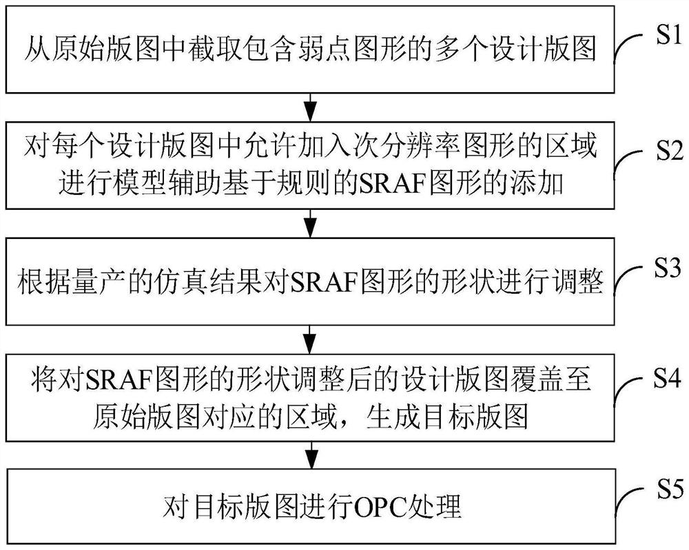
[0065] Such as figure 1 As shown, this embodiment provides a method for adding sub-resolution graphics, the adding method includes the following steps:
[0066] Step S1, intercepting multiple design layouts including weak point graphics from the original layout.
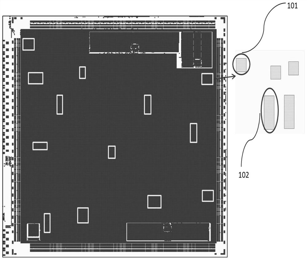
[0067] In this embodiment, the original layout can be a hole-level layout, which is added through multiple rounds of conventional sub-resolution graphics, that is, if there is a graphic spacing in the data layout that meets the addition rules, a sub-resolution of a preset size will be performed. Graphics are added until all graphic spaces are filled with sub-resolution graphics.
[0068] Obtain the weakness graphic library of the process window collected from the existing publication results that cannot meet the mass production requirements, compare the feature maps with the original layout, and screen out multiple design layouts with a small process window (window) that cannot meet the process output requirements ...
Embodiment 2
[0088] On the basis of Embodiment 1, this embodiment provides a method for adding sub-resolution graphics, such as Figure 9 As shown, the flow chart of this embodiment is shown. Compared with embodiment 1, the SRAF graphics also include line graphics, and the step S3 of the adding method also includes:
[0089] Step S33 , dividing the line-shaped figure into a first end area, a second end area, and an associated area.
[0090] Step S34 , determining the range of the second target area according to the area of the first end area; wherein, the second target area partially overlaps with the first end area.
[0091] Step S35 , determining the range of the third target area according to the area of the second end area; wherein, the third target area partially overlaps with the second end area.
[0092] Step S36 , segmenting the long side of the associated area to form a stepped ladder pattern.
[0093] Step S37 , based on the fact that the area corresponding to the stepped ...
Embodiment 3
[0099] This embodiment provides a system for adding sub-resolution graphics, such as Figure 13 As shown, it specifically includes: an acquisition module 20 , an addition module 30 , an adjustment module 40 , an overlay module 50 and an OPC processing module 60 ; the adjustment module 40 includes a first determination unit 41 and a first adjustment unit 42 .
[0100] Wherein, the acquisition module 20 is configured to intercept multiple design layouts including weak point graphics from the original layout.
[0101] In this embodiment, the original layout can be a hole-level layout, which is added through multiple rounds of conventional sub-resolution graphics, that is, if there is a graphic spacing in the data layout that meets the addition rules, a sub-resolution of a preset size will be performed. Graphics are added until all graphic spaces are filled with sub-resolution graphics.
[0102] Obtain the weakness graphic library of the process window collected from the existing p...
PUM
 Abstract
Description
Claims
Application Information
 - R&D
- Intellectual Property
- Life Sciences
- Materials
- Tech Scout
- Unparalleled Data Quality
- Higher Quality Content
- 60% Fewer Hallucinations
Browse by: Latest US Patents, China's latest patents, Technical Efficacy Thesaurus, Application Domain, Technology Topic, Popular Technical Reports.
© 2025 PatSnap. All rights reserved.Legal|Privacy policy|Modern Slavery Act Transparency Statement|Sitemap|About US| Contact US: help@patsnap.com


