U-shaped structure magnetism gathering type permanent magnet motor

A permanent magnet motor and magnetism-concentrating technology, which is applied in the field of U-shaped structure magnetism-concentrating permanent magnet motors, can solve the problems of high additional cost for installation and transportation, increased motor cost, limited power density, etc., and can improve the working point of the magnetic circuit , Inherent friction is reduced, and the overall width is small

Pending Publication Date: 2021-08-31
SUZHOU SEIDAL INTELLIGENT TECH CO LTD
View PDF6 Cites 2 Cited by
  • Summary
  • Abstract
  • Description
  • Claims
  • Application Information

AI Technical Summary

Problems solved by technology

[0004] (1) Power density is limited: existing linear motors generally adopt a stator permanent magnet surface-mounted structure, and it is difficult to further increase the power density;
[0005] (2) The price is extremely expensive: the stator is covered with N-S alternating permanent magnets, because the main components of the permanent magnets are NdFeB or SmCo, which are rare earth materials, which are expensive and scarce, and the stator is covered with rare earth permanent magnets. The price is extremely expensive for long-distance occasions;
[0006] (3) The additional cost of installation and transportation is high: the permanent magnet will generate a strong magnetic field around it, and a special magnetic isolation shield is required in the production process of the stator, which further increases the cost;
[0007] (4) The life of the motor is short: the strong magnetic field on the stator will attract iron filings and dust into the motor when the motor is running, affecting the life of the motor
Although some manufacturers will take measures to prevent dust, such as dust-proof measures such as shielding covers and organ covers, this will undoubtedly increase the cost of the motor;
[0008] (5) Electromagnetic interference: the permanent magnet on the stator will generate a strong magnetic field around it, which will interfere with the normal operation of the surrounding electronic components, resulting in limited application in the field of precision detection in the 3C industry;
[0009] (6) High potential safety hazard: If the powerful permanent magnet is not properly operated during the handling, installation and use of the motor, it will cause workers to be injured

Method used


Image

  • U-shaped structure magnetism gathering type permanent magnet motor
  • U-shaped structure magnetism gathering type permanent magnet motor
  • U-shaped structure magnetism gathering type permanent magnet motor

Examples


Embodiment Construction

[0024] In order to make the technical means, creative features, goals and effects achieved by the present invention easy to understand, the present invention will be further described below in conjunction with a specific implementation example of the present invention.

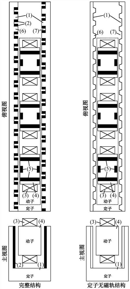
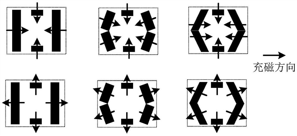
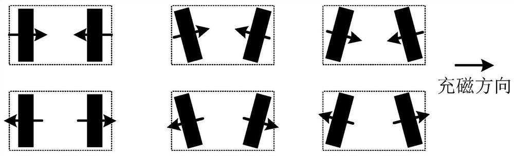
[0025] It includes two parts, the mover and the stator. It is characterized in that: the stator is a U-shaped structure, the mover is embedded in the stator, and there is a certain air gap between the stator and the stator. The stator includes the stator core and the stator magnetic gathering unit, and the mover Including windings, mover cores, and mover magnetic gathering units, a complete mover consists of no less than 3 mover units, each mover unit contains 1 set of windings, 1 mover core and no less than 1 mover magnetism gathering unit, the mover magnetism gathering unit has an O-shaped structure, composed of 4 pieces of permanent magnets, the magnetization direction of all permanent magnets points to the ...


PUM


Abstract

The invention discloses a U-shaped structure magnetism gathering type permanent magnet motor. The permanent magnet motor mainly structurally comprises a rotor and a stator and can be a linear motor or a rotary motor. The permanent magnet motor is mainly characterized in that the stator (mover) is of a U-shaped structure, the mover (stator) is embedded into the U-shaped stator (mover), and a certain air gap is kept between the mover (stator) and the U-shaped stator (mover). The rotor and the stator are provided with a plurality of permanent magnets which are installed according to a characteristic installation mode, a strong magnetic gathering effect is achieved, a magnetic field working point of a main magnetic circuit is remarkably increased, a magnetic leakage coefficient is reduced, then higher thrust density is obtained under the condition of smaller volume and weight, and meanwhile the magnetic field magnetic field magnetic field permanent magnet motor has lower cost and a simpler assembly mode. In addition, by saving the number of permanent magnets on the U-shaped stator (mover), the stator (mover) non-magnetic track motor structure can be simplified into a stator (mover) non-magnetic track motor structure which is lower in cost, simpler to assemble and more suitable for long-stroke occasions.

Description

technical field [0001] The invention relates to the technical field of permanent magnet motors, in particular to a U-shaped structure magnetism-concentrating permanent magnet motor. Background technique [0002] In recent years, with the rapid development of intelligent robots, high-end machine tools, 3C industries, laser cutting, LCD panels, and lithium battery industries, for high-speed, high-precision, and long-stroke linear travel applications, screw or belt-driven Sliding linear motion systems have been difficult to meet the needs of practical applications. Linear motors can directly generate linear motion based on the working principle of traditional rotary motors. They are suitable for working conditions such as long strokes, high precision, high dynamic response, and long life. They have become more and more popular in the market in recent years. [0003] At present, the mainstream solution of linear motor usually adopts permanent magnet linear motor. The working p...

Claims


Application Information

Patent Timeline
Patent Type & Authority Applications(China)
IPC IPC(8): H02K41/02H02K1/06H02K1/17
CPCH02K41/02H02K41/031H02K1/06H02K1/17
Inventor 顾聪盛田田张云龙
Owner SUZHOU SEIDAL INTELLIGENT TECH CO LTD
Why Eureka
Try Eureka