Devices and methods for the diagnosis and treatment of discogenic back pain
A technique for intervertebral disc and back pain, which is applied in the field of diagnosing discogenic back pain, diagnosing and treating discogenic back pain, and can solve problems such as small diagnosis and treatment of discogenic back pain
- Summary
- Abstract
- Description
- Claims
- Application Information
AI Technical Summary
Problems solved by technology
Method used
Image

Examples
example 1
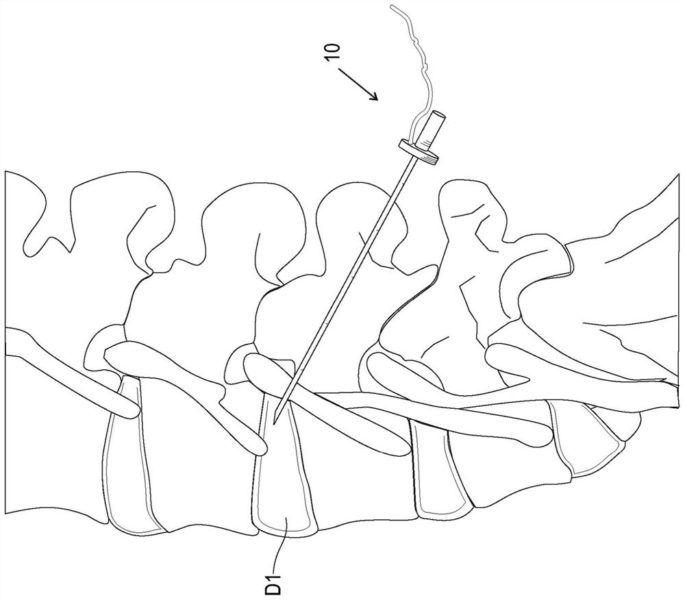
[0096] Example 1: If figure 1 As shown, the cannula of the device (eg, device 10 described herein) will be image-guided towards the dorsolateral annulus fibrosus of disc D1. For the diagnostic phase, the needle will not be advanced beyond the outermost layer of the annulus. The beveled tip of the cannula with integrated electrodes facilitates the separation of the collagen fibers of the annulus when the device is rotated parallel to the sheets of the annulus. Constant current pulses in the range of 2 to about 20 mAMP will be delivered to the outer annulus fibrosus. Consistent pain, especially evoked at the lower end of the current range, is consistent with nerve ending sensitivity and discogenic pain (eg, positive diagnosis). A syringe can then be engaged with the port of the device to administer the local anesthetic. The device can then be advanced to deliver therapeutic agents, such as anti-inflammatory drugs and / or neurotoxins, and then repositioned in a manner consisten...
example 2
[0097] Example Two: Sprague Doré rats were tested for compound action potentials evoked from the caudal disc 5 (tail) of the lumbar spinal cord when current was delivered from the device 10 to the site. After a 10mAMP current pulse is fired from the device into the primitive caudal disc, the complex evoked potential reaches the spinal cord, with an initial peak corresponding to a nerve conduction velocity (NCV) of about 8 m / s and a second peak corresponding to a nerve conduction velocity (NCV) of about 5 m / s, as Figure 5A shown. Inject 2% lidocaine (10 μL) into the intervertebral disc for at least 30 minutes to completely eliminate the evoked potential, such as Figure 5B shown.
example 3
[0098] Example Three: A test was performed to assess whether a change in position (eg, spinal flexion) would be beneficial in establishing a diagnosis of discogenic pain. For example, it was hypothesized that flexing the spine during diagnosis could potentially amplify differences in evoked potential thresholds between healthy and symptomatic discs when the patient is in a non-neutral position.
[0099] Such as Figure 6A As indicated, 8 mAMP current pulses were applied to the mid-positioned tail disc of Sprague-Dorrey rats. No eliciting compounds were detected in the lumbar spinal cord. However, if Figure 6B As shown, when the rat's tail was subsequently flexed to apply a mixed compressive / tensile strain on the caudal disc 5, the 8 mAMP pulse did produce a mixed potential that was distinguishable from noise. The results indicate that differences between healthy and symptomatic discs in the threshold current or evoked potential required to elicit consistent pain may be amp...
PUM
 Abstract
Description
Claims
Application Information
 - R&D
- Intellectual Property
- Life Sciences
- Materials
- Tech Scout
- Unparalleled Data Quality
- Higher Quality Content
- 60% Fewer Hallucinations
Browse by: Latest US Patents, China's latest patents, Technical Efficacy Thesaurus, Application Domain, Technology Topic, Popular Technical Reports.
© 2025 PatSnap. All rights reserved.Legal|Privacy policy|Modern Slavery Act Transparency Statement|Sitemap|About US| Contact US: help@patsnap.com