Portable forestry scarifier

A kind of loosening machine and portable technology, applied in agricultural machinery and tools, agricultural, land preparation machinery, etc., can solve the problems of single working mode, inability to adjust forest adaptability, difficulty in both high loosening efficiency and versatility, and achieve Large single loosening area, improved loosening quality, high passability effect

Active Publication Date: 2021-09-03
NANCHANG INST OF TECH
View PDF5 Cites 2 Cited by
  • Summary
  • Abstract
  • Description
  • Claims
  • Application Information

AI Technical Summary

Problems solved by technology

[0003]Existing forestry scarifiers only have a single working mode and cannot be adjusted according to the row spacing of the forest, so it is difficult to achieve both high scarification efficiency and High versatility

Method used


Image

  • Portable forestry scarifier
  • Portable forestry scarifier
  • Portable forestry scarifier

Examples


Embodiment 1

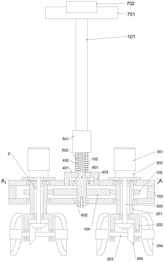
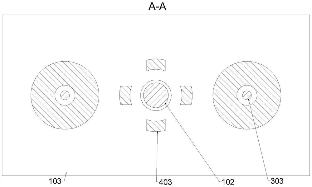
[0026] Such as figure 1 As shown, a kind of portable forestry ripper provided by the present invention comprises: pull rod 101, steering shaft 102 mounting box 103, first gear 104 and two soil turning mechanisms 2, pull rod 101; Steering shaft 102 and described pull rod 101 One end is fixedly connected; the installation box 103 is provided with a first through hole, and the shaft body of the steering shaft 102 is connected with the bearing of the installation box 103; the first gear 104 is arranged in the installation box 103, and the first gear 104 is fixedly connected to the steering shaft 102 shaft body; two soil turning mechanisms 2 are distributed on both sides of the first gear 104, and the installation box 103 is respectively provided with an installation through hole on both sides of the first gear 104, and the two soil turning mechanisms 2 are respectively bearing connected to the first gear 104. In the installation through holes on both sides of the gear 104, the two...

Embodiment 2

[0031] On the basis of Embodiment 1, after the working mode of the whole scarifier is switched, the working direction of the scarifier does not change after the tiller mechanism 2 rotates 180 degrees.

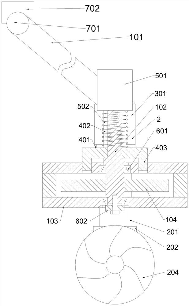
[0032] Such as figure 1 and 2As shown, wherein, the soil turning mechanism 2 includes a connecting pipe 201, a fork frame 202, a transmission shaft 203, a soil loosening wheel 204 and a power unit, the outer wall of the connecting pipe 201 is connected with the installation through-hole bearing, and the second The second gear 105 is fixedly connected to the body of the connecting pipe 201, and the connecting pipe 201 is positioned at one end of the lower side of the installation box 103 and is fixedly connected with the fork frame 202, the fork frame 202 is connected with the transmission shaft 203 bearings, and the soil loosening wheel 204 is fixedly connected with the transmission shaft 203, and the transmission shaft 203 is tooth-connected with a power device, and the power...

Embodiment 3

[0035] On the basis of Embodiment 2, in order to ensure that the scarifier is switched between working modes, the power device is always connected to the transmission device.

[0036] Such as figure 1 As shown, wherein, the power device includes a motor 301, a reducer 302 and an output shaft 303, the motor 301 is fixedly connected to the upper surface of the installation box 103, the output end of the motor 301 is connected to the input end of the reducer 302 connection, the output end of the reducer 302 is connected to the output shaft 303, the fork frame 202 is provided with a second through hole, the output shaft 303 is coaxial with the connecting pipe 201, and the output shaft 303 passes through the connection The pipe hole and the second through hole of the pipe 201 are gear-connected with the transmission shaft 203 through the bevel gear 304 , and the shaft body of the transmission shaft 203 is connected with the inner wall of the connecting pipe 201 with a bearing.

[...


PUM


Abstract

The invention discloses a portable forestry scarifier, and belongs to the technical field of agricultural machinery. The portable forestry scarifier comprises a pull rod, a steering shaft, a mounting box, a first gear and two soil turning mechanisms, wherein the steering shaft is fixedly connected with one end of the pull rod; the mounting box is provided with a first through hole, and a body of the steering shaft is in bearing connection with the mounting box; the first gear is fixedly connected to the body of the steering shaft; and the two soil turning mechanisms are distributed on the two sides of the first gear, mounting through holes are formed in the positions, located on the two sides of the first gear, of the mounting box respectively, the two soil turning mechanisms are in bearing connection with the interiors of the mounting through holes in the two sides of the first gear, the two soil turning mechanisms are each provided with a second gear, each second gear is in toothed connection with the first gear, and the number of teeth of the first gear is even times that of teeth of the second gears. According to the portable forestry scarifier, by switching the working modes of the whole scarifier, higher scarification efficiency can be achieved when the forest row spacing is wider, and higher trafficability is achieved when the forest row spacing is narrower.

Description

technical field [0001] The invention relates to the technical field of agricultural machinery, in particular to a portable forestry scarifier. Background technique [0002] The growth and planting of forest trees requires regular soil loosening operations to maintain the oxygen breathing of the roots of the trees. Regular loose soil can increase the oxygen content in the soil and promote plant growth. Nowadays, the popularization of agricultural mechanization is relatively high, and most of the soil loosening operations are completed by soil scarifiers. The row spacing of tree planting has a great relationship with the species of trees, and different tree species have different planting row spacing. [0003] Existing forestry loosening machines only have a single working mode and cannot be adjusted adaptively according to the row spacing of forests, so it is difficult to have both high loosening efficiency and high versatility. Contents of the invention [0004] The purp...

Claims


Application Information

Patent Timeline
Patent Type & Authority Applications(China)
IPC IPC(8): A01B39/08A01B39/22A01B39/20
CPCA01B39/085A01B39/22A01B39/20
Inventor 吴春生
Owner NANCHANG INST OF TECH
Why Eureka
Try Eureka