Vamp hot press molding equipment and use method thereof

A technology for hot-press forming and shoe uppers, which is applied in mechanical equipment, footwear, applications, etc., and can solve problems such as easy adhesion of shoe uppers to the support plate, increased difficulty in removing shoe uppers, and easy burns to operators, etc. Achieve the effects of improving the effect of hot pressing forming, rapid cooling, and improving the quality of forming

Inactive Publication Date: 2021-09-03
阜阳和益鞋业有限公司
View PDF6 Cites 1 Cited by
  • Summary
  • Abstract
  • Description
  • Claims
  • Application Information

AI Technical Summary

Problems solved by technology

[0005] The object of the present invention is to provide a shoe upper thermoforming equipment and its use method. The cooling liquid is fed into the cooling cavity through the liquid inlet pipe. The coolant in the cooling chamber can quickly cool down the upper, which is convenient for subsequent removal of the upper and avoids harm to the operator during the removal process. The inclined surface of the movable table is squeezed by the rollers, and the first extrusion rod, Under the combined action of the sliding block, the second extruding rod, the cross bar and the push rod, the jacking block moves upwards and lifts the upper so that the upper is separated from the support plate, which is more helpful for the operator to remove the upper , and the cooling liquid can be recycled, and the downward impact force of the connecting seat can be buffered to a certain extent, so as to avoid the damage of the shoe upper caused by the excessive downward pressure of the pressing plate assembly, which is beneficial to improve the quality of hot pressing forming and solve the problem of At present, after hot pressing, the temperature on the surface of the shoe upper and the supporting plate is relatively high, and it is easy to burn the operator during the removal process. On the pallet, it further increases the difficulty of taking out the shoe upper

Method used


Image

  • Vamp hot press molding equipment and use method thereof
  • Vamp hot press molding equipment and use method thereof
  • Vamp hot press molding equipment and use method thereof

Examples


Embodiment 1

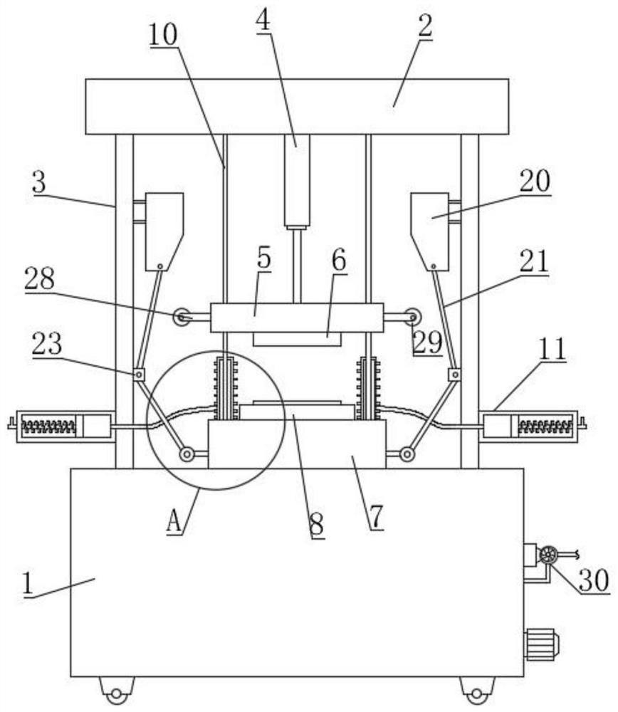
[0046] like Figure 1-5 As shown, a shoe upper thermoforming equipment proposed by the present invention includes a fixed box 1, a top plate 2, a vertical plate 3, a lifting cylinder 4, a connecting seat 5, a pressing plate assembly 6, a fixing seat 7 and a supporting plate 9, and the fixed The bottom of the box 1 is equipped with traveling wheels, which are driven by electricity. The equipment can be easily moved by setting the traveling wheels. The top plate 2 is horizontally set above the fixed box 1. The top sides of the fixed box 1 are fixed with vertical plates by bolts. 3. The top of the vertical plate 3 is fixedly connected with the top plate 2 by bolts, and the bottom of the top plate 2 is fixedly installed with a lifting cylinder 4, and the bottom end of the lifting cylinder 4 is connected with the connecting seat 5, and the lifting cylinder 4 is used to raise and lower the connecting seat 5 , the fixed base 7 is fixedly installed on the top of the fixed box 1 by bol...

Embodiment 2

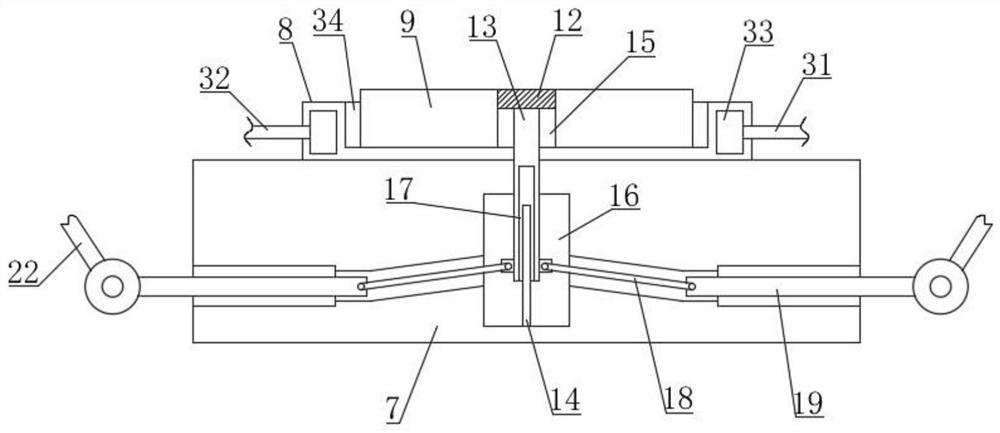
[0049] like Figure 6-8 As shown, the difference between this embodiment and Embodiment 1 is that a liquid storage chamber 35 is provided in the fixed box 1, and a liquid suction pump 30 is fixedly installed on the fixed box 1 through a mounting seat, and the liquid suction pump 30 is provided with an input pipe and Output pipe, the other end of the input pipe is communicated with the liquid storage chamber 35, the other end of the output pipe is connected with the liquid inlet pipe 31, the other end of the liquid outlet pipe 32 is communicated with the liquid storage chamber 35, and the liquid suction pump 30 connects the liquid storage chamber 35 The cooling liquid in the cooling chamber is delivered to the liquid inlet pipe 31, and the cooling liquid after absorbing heat in the cooling chamber 33 flows back into the liquid storage chamber 35 through the liquid outlet pipe 32; a temperature sensor is installed in the liquid storage chamber 35, and the temperature sensor is us...

Embodiment 3

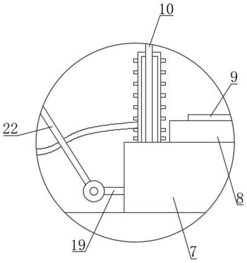
[0053] like Figure 9-10 As shown, the difference between this embodiment and Embodiment 1 and Embodiment 2 is that an anti-shock assembly 11 is installed between the connecting seat 5 and the fixed seat 7, the anti-shock assembly 11 is located on both sides of the cooling table 8, and the anti-shock assembly 11 Multiple sets are provided on each side, and the anti-shock assembly 11 includes an elastic bellows 1101, a vent pipe 1102, a connecting cylinder 1103, a piston 1104, a second spring 1105, a movable rod 1106, and a limit protrusion 1107; the elastic bellows 1101 is vertically The connecting cylinder 1103 is arranged horizontally and fixed on the vertical plate 3 by bolts, the piston 1104 is movably arranged in the connecting cylinder 1103, and the connecting cylinder 1103 limits the position of the piston 1104 so that the piston 1104 is connected Sliding inside the cylinder 1103, the movable rod 1106 is horizontally arranged on the piston 1104, and the other end of the...


PUM


Abstract

The invention belongs to the technical field of vamp processing, and aims to solve the problems that at present, after hot press molding, the temperatures of the surfaces of a vamp and a bearing plate are high, operators are easily scalded in the taking-out process, the vamp is inconvenient to take down, the vamp is easily adhered to the bearing plate due to hot press molding, and the vamp taking-out difficulty is further increased. The vamp hot press molding equipment comprises a fixing box, a pressing plate assembly and a bearing plate, a lifting air cylinder is installed at the bottom of a top plate, the bottom end of the lifting air cylinder is connected with a connecting base, the pressing plate assembly is installed at the bottom of the connecting base, a cooling table is installed at the top of the fixing box, a containing groove is formed in the cooling table, the bearing plate is located in the containing groove, and a groove is formed in the bearing plate. According to the vamp hot press molding equipment, the vamp can be rapidly cooled, harm to operators in the taking-out process is avoided, the vamp can be jacked up so that the vamp can be separated from the bearing plate, and the operators can take down the vamp conveniently.

Description

technical field [0001] The invention relates to the technical field of shoe upper processing, in particular to a shoe upper hot-press forming equipment and a method for using the same. Background technique [0002] In recent years, with the advancement of textile technology, it is a relatively common method to shape the upper by hot pressing. The hot pressing operation of the upper is generally completed by hot pressing equipment. The hot pressing machine generally includes a hot pressing plate And the working board, when operating, place the shoe upper to be processed on the working board, press down the shoe face on the working board through the hot pressing plate for hot pressing and shaping, and then heat-form the shoe upper Just take it out; [0003] In the specific use process, after the hot-press forming operation is completed, it generally needs to be taken out manually, but because the surface temperature of the hot-pressed shoe upper is high, it is inconvenient fo...

Claims


Application Information

Patent Timeline
Patent Type & Authority Applications(China)
IPC IPC(8): A43D8/00F16F15/067
CPCA43D8/00F16F15/067
Inventor 高领王家健张圣权高翔姜玉金
Owner 阜阳和益鞋业有限公司
Why Eureka
Try Eureka