Needle insertion device for puncture needle

A puncture needle and needle insertion technology, which is applied in the field of multi-degree-of-freedom needle puncture needle devices with external motors, can solve the problems of impracticality, accurate positioning errors, etc.

Pending Publication Date: 2021-09-03
ZHEJIANG UNIV
View PDF0 Cites 0 Cited by
  • Summary
  • Abstract
  • Description
  • Claims
  • Application Information

AI Technical Summary

Problems solved by technology

However, CT-guided puncture also has disadvantages: because it is not timely imaging, breathing movement will cause errors in accurate positioning, and the human body must be trained to master the phase of breathing.
[0004] In practical applications, it is often necessary to perform surgery under the guidance of CT, and since the puncture needle needs to penetrate into the lungs of the human body, in order to ensure that the lesion area can be reached, the feeding device needs to provide a sufficiently large puncture stroke, and the feeding device itself cannot Occupies too much space to adapt to the narrow space of the CT bed; in order to ensure that the lesion area can be reached, the rotation device needs to provide a rotation angle of at least 180°; due to respiration, there will be slight fluctuations on the surface of the human chest cavity, the device needs to provide a certain Height adjustment function; while meeting the above three requirements, the device needs to be compatible with CT, so the device cannot use any metal materials to eliminate the impact of metal on the image quality of CT imaging

Method used


Image

  • Needle insertion device for puncture needle
  • Needle insertion device for puncture needle
  • Needle insertion device for puncture needle

Examples


Embodiment Construction

[0052] The present invention will be further described below in conjunction with the accompanying drawings and specific implementations.

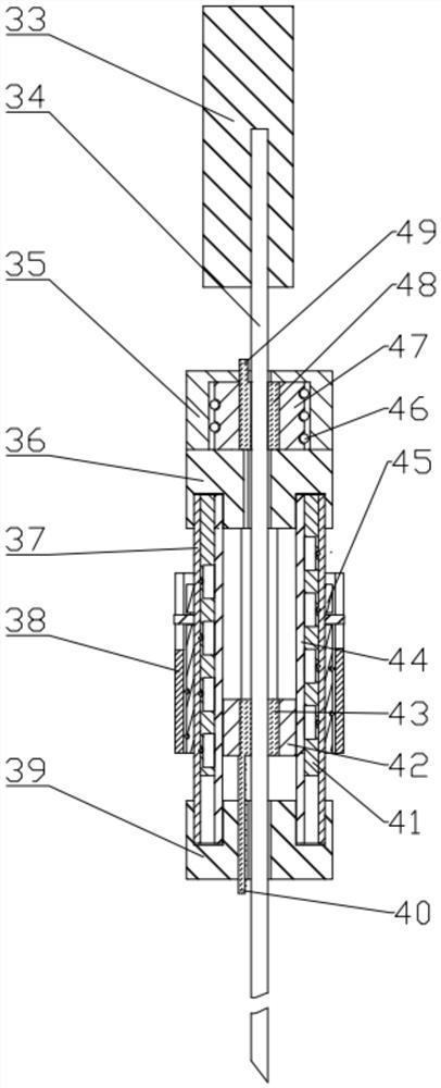
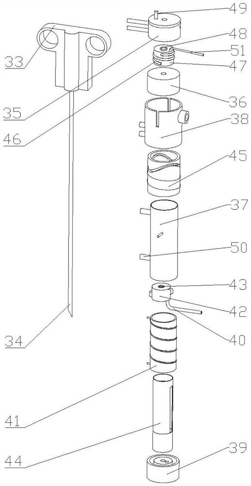
[0053] like image 3 As shown, the biopsy needle is mainly composed of a biopsy gun 33 at the upper end and a biopsy needle 34 at the lower end; the biopsy gun 34 is used to control the biopsy needle 34 for tissue sampling, and drives the inner needle to complete the biopsy; the biopsy needle pierces the human lungs , extract living tissue.

[0054] A biopsy puncture needle is installed on the needle feeding device; the lifting and feeding of the biopsy puncturing needle and the angle around the needle axis are adjusted and controlled by the needle feeding device.

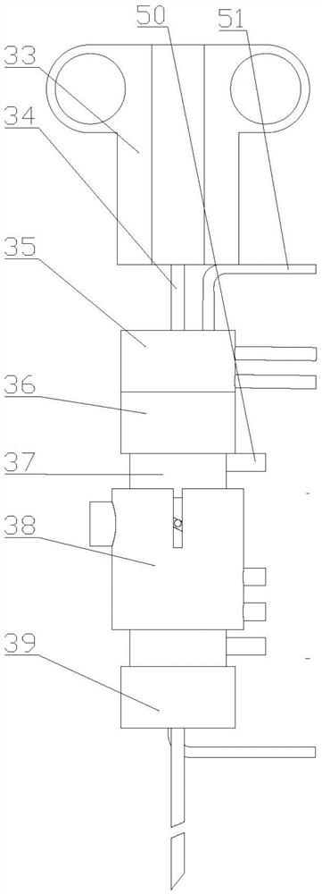
[0055] like Figure 1-Figure 3 As shown, the needle feeding device includes a rotating module housing 35, a feeding module upper end cover 36, a feeding module housing 37, a needle cylinder housing 38, a feeding module lower end cap 39, an internally threaded tube 41, an inter...


PUM


Abstract

The invention discloses a needle insertion device for a puncture needle. A biopsy puncture needle is mounted on the needle insertion device. The needle insertion device comprises a rotary module shell, a feeding module shell, a needle cylinder shell, an internally-threaded tube, an internally-threaded slider, an internally-threaded slider guide tube, a disc cam sleeve and a rotary inner column which are nested mutually; a rotating column guide rope winds the rotary inner column, the internally-threaded tube and the disc cam sleeve, threads out the rotary module shell and then is connected with an external driving shaft to form a linear driving mechanism so as to drive rotation; and the internally-threaded slider bulges to penetrate through the internally-threaded slider guide tube and is embedded into the internally-threaded tube, the feeding module shell bulges to penetrate through the needle cylinder shell and is embedded into the disc cam sleeve, and rotary inner column airbags are arranged among the internally-threaded slider, the rotary inner column and the biopsy puncture needle. According to the needle insertion device for the puncture needle, CT imaging compatible with a surgical operation process can be achieved under the condition that a metallic dense substance is absent in a CT section during needle puncture surgical operation, the feeding and rotating control of the puncture needle can be achieved, and a distance of a needle cylinder relative to a human body height can be controlled to not change along with respiratory movement.

Description

technical field [0001] The invention belongs to a needle insertion device in a needle puncture-assisted surgical robot, which belongs to the field of medical device manufacturing and application, and specifically relates to a CT-compatible external motor-mounted multi-degree-of-freedom needle puncture needle device. Background technique [0002] Clinically, if a lung lesion is found by CT examination, but it is not sure whether it is caused by infection, non-lesion infection, or tumor, especially if malignant tumor cannot be ruled out, a lung biopsy is required to clarify the nature of the lesion. Lung puncture is also performed under the positioning of CT to puncture the lesion to take out some tissues for routine examination. However, CT-guided puncture also has shortcomings: because the imaging is not timely, the breathing movement will cause errors in accurate positioning, and the human body must be trained to master the breathing phase. When the puncture needle needs t...

Claims


Application Information

Patent Timeline
Patent Type & Authority Applications(China)
IPC IPC(8): A61B10/02A61B17/34A61B34/30
CPCA61B10/0233A61B17/34A61B34/30A61B2017/3405
Inventor 雷勇王真
Owner ZHEJIANG UNIV
Why Eureka
Try Eureka