Metal garbage crusher

A shredder and garbage technology, applied in the field of metal processing, can solve the problems affecting the efficiency of crushing, throwing out, affecting the crushing effect, etc., to achieve the effect of ensuring effect and safety, and improving efficiency

Active Publication Date: 2021-09-03
山东德隆博德尔环保装备发展有限公司
View PDF5 Cites 4 Cited by
  • Summary
  • Abstract
  • Description
  • Claims
  • Application Information

AI Technical Summary

Problems solved by technology

[0003] 1. During the crushing process, the mutual rotation between the knife rollers is used to crush the metal. In this way, the crushing knife will be subjected to a large force when crushing the metal, so that it will be greatly reduced when crushing the harder metal. Its service life, and some metal wastes will roll continuously on both sides due to the limitation of their shape during the crushing process and cannot roll to the middle part for crushing, which will affect the crushing efficiency;
[0004] 2. The crushing of the crusher is the way of mechanical extrusion and tearing. Although it can break the metal, it will deform the metal and make some flake metal adhere to the surface of the crushing knife, thus affecting its subsequent crushing effect. , and the metal adhering to the surface of the crushing knife may be thrown out with the rotation of the knife roller, which is also dangerous

Method used


Image

  • Metal garbage crusher
  • Metal garbage crusher
  • Metal garbage crusher

Examples


Embodiment Construction

[0020] The following will clearly and completely describe the technical solutions in the embodiments of the present invention with reference to the accompanying drawings in the embodiments of the present invention. Obviously, the described embodiments are only some, not all, embodiments of the present invention. Based on the embodiments of the present invention, all other embodiments obtained by persons of ordinary skill in the art without making creative efforts belong to the protection scope of the present invention.

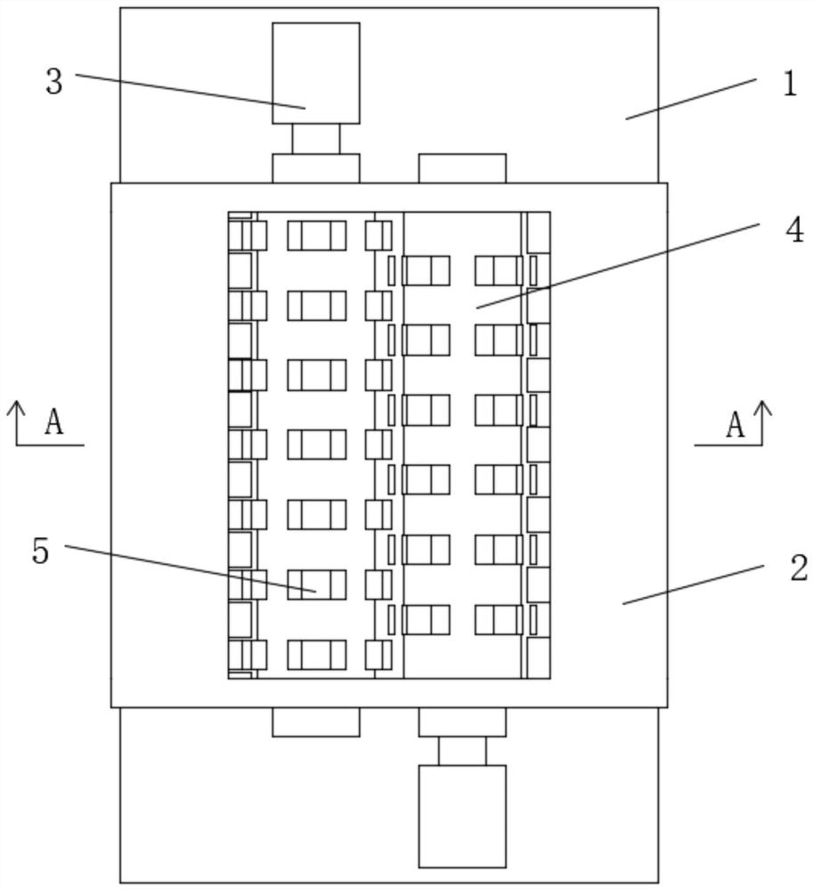
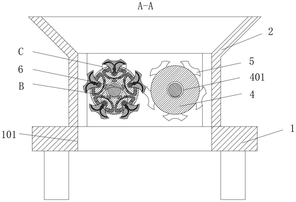
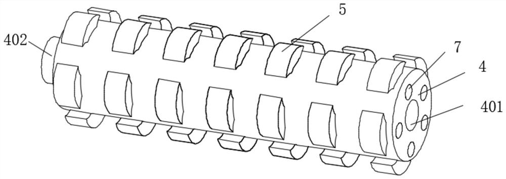
[0021] see Figure 1-5 , a metal waste crusher, comprising a machine base 1, a crushing box 2 is fixedly installed on the top of the machine base 1, and the bottom of the machine base 1 is located at the bottom of the crushing box 2. For the material receiving device, forward and reverse motors 3 are fixedly installed on both sides of the crushing box 2, and the forward and reverse rotation of the knife roller 4 can be realized by using the forward and reverse...


PUM


Abstract

The invention relates to the technical field of metal processing, and discloses a metal garbage crusher. Forward and reverse rotation motors are fixedly mounted on the two sides of a crushing box correspondingly, two cutter rollers are movably mounted in the crushing box, movable grooves are uniformly formed in the outer rings of the cutter rollers, and crushing cutters are movably mounted in the movable grooves. A gear shaft with one end fixed to the crushing box is fixedly installed in each middle hole, a hydraulic transmission cavity is formed in the position, located at the bottom of each crushing cutter, in the corresponding cutter roller, a sliding block is movably in cup joint with the middle of each hydraulic transmission cavity, and a transmission gear is movably installed in the position, located between the corresponding middle hole and the corresponding hydraulic transmission cavity, in each cutter roller. A through type positioning column is fixedly in cup joint with each sleeve hole, hydraulic holes are formed in the crushing cutters towards the two sides, and the outer side ends of the hydraulic holes are movably in cup joint with jacking strips. By changing the mounting mode of the crushing cutters on the cutter rollers and the internal structure, the service life of the crushing cutters is prolonged, the crushing effect of the crushing cutters is improved , and meanwhile safety is higher.

Description

technical field [0001] The invention relates to the technical field of metal processing, in particular to a metal waste shredder. Background technique [0002] Nowadays, there are more and more metal products, and they also become metal waste after use or scrap. Metal materials can be recycled and reused, which not only solves the problem of waste but also realizes the utilization of resources. The recycling of metal waste must be carried out first. Crushing treatment, breaking large and irregular metal waste into small pieces of sheet metal, the equipment used is a metal crusher, which uses the rotation of the knife roller to squeeze and shred the metal, etc. The physical effect makes it become a small piece of sheet metal, which is convenient to use and simple in structure, but there are still certain problems: [0003] 1. During the crushing process, the mutual rotation between the knife rollers is used to crush the metal. In this way, the crushing knife will be subjecte...

Claims


Application Information

Patent Timeline
Patent Type & Authority Applications(China)
IPC IPC(8): B02C4/08B02C4/30B02C4/40B02C18/14B02C18/18B02C18/16
CPCB02C4/08B02C4/30B02C4/40B02C18/142B02C18/18B02C18/16B02C18/0084B02C2201/06Y02P10/20
Inventor 张磊
Owner 山东德隆博德尔环保装备发展有限公司
Why Eureka
Try Eureka