
Rotary shearing cavitation nozzle

A rotary shearing and nozzle technology, applied in the field of water jet, can solve the problems of poor cavitation effect, small cavitation area, and restrict the efficient application of cavitation jet, and achieve the effect of increasing the volume and increasing the cavitation effect.

Active Publication Date: 2021-09-03
WUHAN UNIV
View PDF10 Cites 1 Cited by
  • Summary
  • Abstract
  • Description
  • Claims
  • Application Information

AI Technical Summary

Problems solved by technology

However, the existing cavitation nozzles have problems such as poor cavitation effect and small cavitation area. It is of great significance to invent a cavitation nozzle with strong cavitation effect and large cavitation area.
[0005] In the traditional center-body cavitation nozzle, the cavitation occurs mainly in the flow-around cavitation, and the cavitation only occurs at the end of the center body. After the jet is ejected from the nozzle, the cavitation effect is difficult to maintain due to changes in the external environment. , leading to poor cavitation effect and small volume of cavitation cloud
This undoubtedly greatly limits the efficient application of cavitation jet

Method used


Image

  • Rotary shearing cavitation nozzle
  • Rotary shearing cavitation nozzle
  • Rotary shearing cavitation nozzle

Examples


Embodiment Construction

[0036] The technical solution of the present invention will be clearly and completely described below in conjunction with the accompanying drawings. In the description of the present invention, it should be noted that the terms "center", "upper", "lower", "left", "right", "vertical", "horizontal", "inner", "outer" etc. The indicated orientation or positional relationship is based on the orientation or positional relationship shown in the drawings, and is only for the convenience of describing the present invention and simplification of the description, rather than indicating or implying that the referred device or element must have a specific orientation. construction and operation, therefore, should not be construed as limiting the invention. In addition, the terms "first", "second", and "third" are used for descriptive purposes only, and should not be construed as indicating or implying relative importance.

[0037] In the description of the present invention, it should be ...


PUM


Abstract

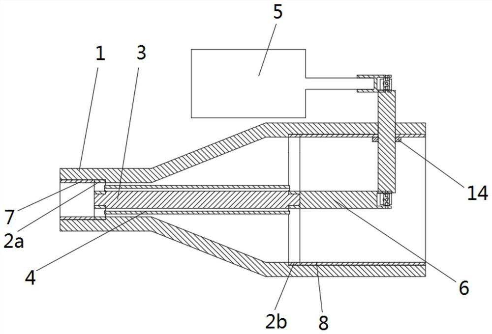
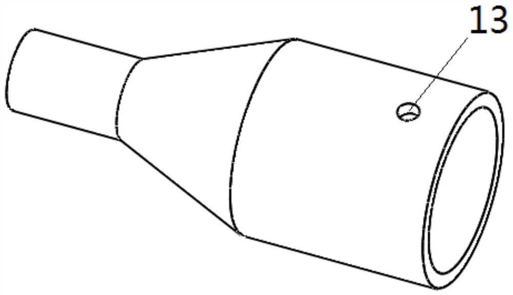
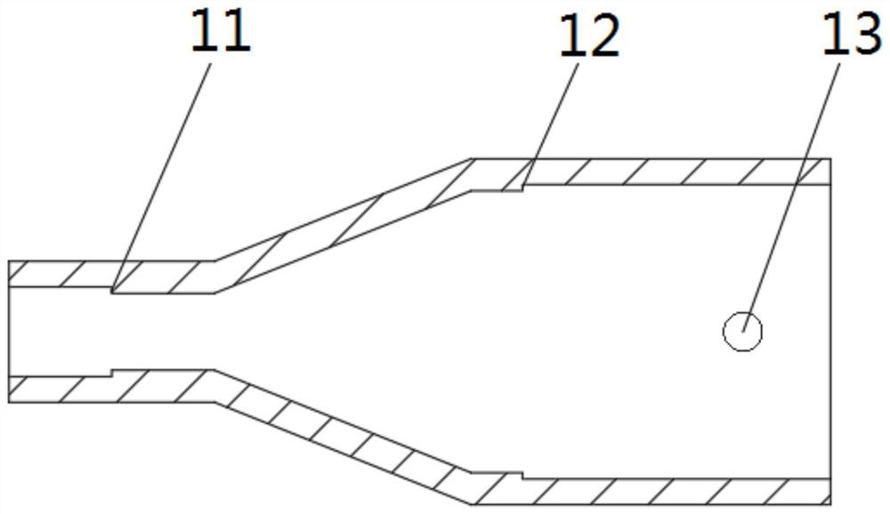
The invention provides a rotary shearing cavitation nozzle, and belongs to the technical field of water jets. The rotary shearing cavitation nozzle comprises a nozzle main body, a first support, a second support, a central body, a rotary shearing cylinder, a driving motor and a universal shaft; the nozzle main body is of a hollow rotating body structure, and the inner diameter of the water inlet end is larger than that of the water outlet end; the first support and the second support are oppositely and rotationally mounted in the nozzle main body, and the two ends of the central body are rotationally mounted on the first support and the second support respectively; the central body is sleeved with the rotary shearing cylinder, and the two ends of the rotary shearing cylinder are fixed to the first support and the second support respectively; the output end of the driving motor is connected with the input end of the universal shaft, and the output end of the universal shaft is connected with the second support. According to the nozzle, the outside of the central body of the central body type nozzle is coaxially sleeved with the rotary shearing cylinder, and the jet flow between the rotary shearing cylinder and the central body generates a speed gradient in the radial direction due to high-speed rotation of the rotary shearing cylinder, so that the maximum principal stress in liquid becomes tension, and the liquid is severely cavitated.

Description

technical field [0001] The invention relates to the technical field of water jets, in particular to a rotary shear cavitation nozzle. Background technique [0002] Water jet is to use high pressure or ultra high pressure pump to pressurize ordinary water medium, and then make it spray out through the nozzle at subsonic speed, sonic speed or supersonic speed, thus forming high-speed water flow, which has excellent performance in cleaning, cutting, etc., and has become more and more popular. People's favor. [0003] Cavitation refers to gasification and formation of bubbles due to the partial pressure of the liquid being lower than the saturated vapor pressure of the liquid, that is, the explosive growth of gas nuclei. The cavitation will generate high temperature, high pressure and micro jets at the moment of collapse, accompanied by complex physicochemical and electrochemical reactions. In the prior art, the cavitation nozzle made by adopting this principle has the advanta...

Claims


Application Information

Patent Timeline
Patent Type & Authority Applications(China)
IPC IPC(8): B05B3/02B08B3/02
CPCB05B3/02B08B3/02
Inventor 李登姚致远巫世晶康勇罗文悦熊杰
Owner WUHAN UNIV
Learn More