Automatic workpiece clamping device for industrial machining

A workpiece and industrial technology, applied in the field of automatic workpiece clamping devices for industrial processing, can solve the problems of unadjustable clamping range and low practicability of mechanical claw, achieve flexible and adjustable clamping range, protect workpiece, and avoid falling off. Effect

Inactive Publication Date: 2021-09-03
苏州君洹自动化设备有限公司
View PDF1 Cites 0 Cited by
  • Summary
  • Abstract
  • Description
  • Claims
  • Application Information

AI Technical Summary

Problems solved by technology

[0004] The object of the present invention is to provide an automatic workpiece clamping device for industrial processing, which includes a housing, a working chamber is arranged in the housing, a positioning seat is arranged in the middle of the working chamber, a driving assembly is arranged on the top of the working chamber, and the driving assembly is connected with Auxiliary component, the auxiliary component is connected with a clamping component to solve the problem that the clamping range of the mechanical claw of the existing device cannot be adjusted, which leads to the problem of low practicability of the device

Method used


Image

  • Automatic workpiece clamping device for industrial machining
  • Automatic workpiece clamping device for industrial machining
  • Automatic workpiece clamping device for industrial machining

Examples


Embodiment 1

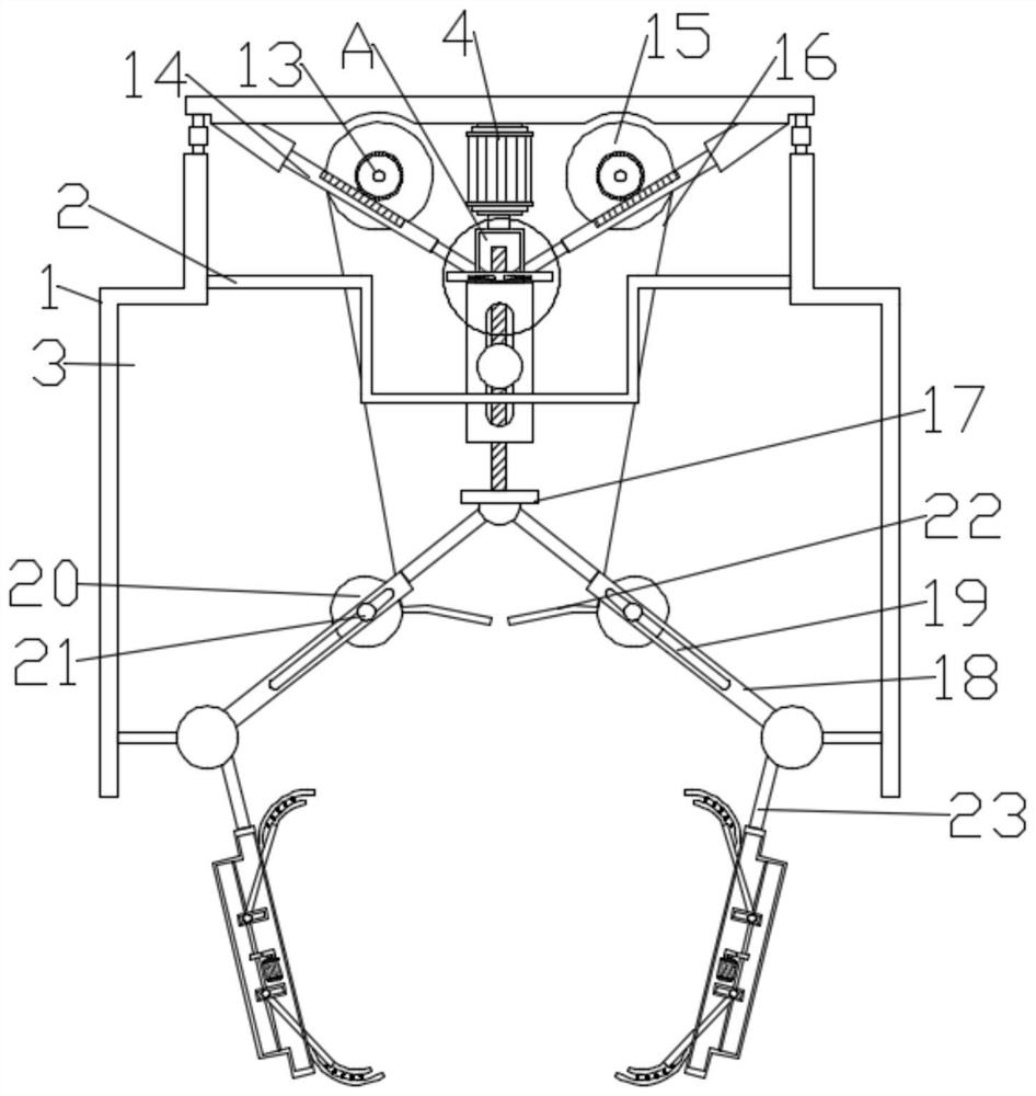
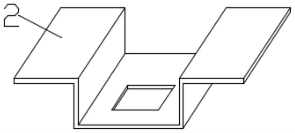
[0024] Such as Figure 1-2 As shown, in the embodiment of the present invention, an automatic workpiece clamping device for industrial processing includes a housing 1, a working chamber 3 is arranged in the housing 1, a positioning seat 2 is arranged in the middle of the working chamber 3, and a positioning seat 2 is arranged in the middle of the working chamber 3. The top is provided with a driving assembly, the driving assembly is connected with an auxiliary assembly, and the auxiliary assembly is connected with a clamping assembly 23;

[0025] The drive assembly includes a first working motor 4 and an internally threaded sleeve 5, the first working motor 4 is fixedly mounted on the top of the housing 1, and the output end of the first working motor 4 is fixedly connected with the internally threaded sleeve 5, and the internally threaded sleeve The barrel 5 is sleeved on the outside of the first screw 6, and the internally threaded sleeve 5 and the first screw 6 are threaded...

Embodiment 2

[0032] Such as Figure 1-2 As shown, in the embodiment of the present invention, an automatic workpiece clamping device for industrial processing includes a housing 1, a working chamber 3 is arranged in the housing 1, a positioning seat 2 is arranged in the middle of the working chamber 3, and a positioning seat 2 is arranged in the middle of the working chamber 3. The top is provided with a driving assembly, the driving assembly is connected with an auxiliary assembly, and the auxiliary assembly is connected with a clamping assembly 23;

[0033]The drive assembly includes a first working motor 4 and an internally threaded sleeve 5, the first working motor 4 is fixedly mounted on the top of the housing 1, and the output end of the first working motor 4 is fixedly connected with the internally threaded sleeve 5, and the internally threaded sleeve The barrel 5 is sleeved on the outside of the first screw 6, and the internally threaded sleeve 5 and the first screw 6 are threadedl...


PUM


Abstract

The invention discloses an automatic workpiece clamping device for industrial machining, belongs to the technical field of automation, and solves the problem that the clamping range of a mechanical claw of an existing device cannot be adjusted, so that the practicability of the device is low. The device comprises a shell, a working cavity is formed in the shell, a positioning seat is arranged in the middle of the working cavity, a driving assembly is arranged at the top of the working cavity, the driving assembly is connected with an auxiliary assembly, and the auxiliary assembly is connected with a clamping assembly. The device is provided with a grabbing assembly, due to the grabbing assembly, workpiece grabbing is achieved, falling of workpieces with types can be avoided, through the arrangement of a pressing plate, clamping and limiting of a workpiece are achieved, meanwhile, the effect of protecting the workpiece can be achieved, meanwhile, the clamping range of the clamping assembly is flexible and adjustable, and the application range of the device is widened.

Description

technical field [0001] The invention relates to the technical field of automation, in particular to an automatic workpiece clamping device for industrial processing. Background technique [0002] In the process of industrial automation production, manipulators are needed in many places. Most of the solutions are realized by using cylinders supplemented by corresponding fixtures. The structure is more complicated, the design cycle is longer, the production and processing are complicated, and the installation is cumbersome. , low accuracy, low efficiency, and the manipulator is not reliable in grabbing materials. [0003] Chinese patent CN203712715U discloses an automatic clamping device. The power automation module includes a power shaft, a housing, a rail rack I and a rail rack II, and two vertically opposite sides of the housing are provided with mounting holes for the power shaft. Bearings are installed at both ends of the power shaft, and the bearings are installed on th...

Claims


Application Information

Patent Timeline
IPC IPC(8): B25J15/00
CPCB25J15/00
Inventor 不公告发明人
Owner 苏州君洹自动化设备有限公司
Why Eureka
Try Eureka