[0059] In order to make the technical problem solved by the present invention, the technical solution used in the art is more clear, and the technical solutions of the embodiments will be further described in connection with the accompanying drawings, which will be described in detail. Part of embodiments, not all embodiments. Based on the embodiments of the present invention, those skilled in the art are in the range of the present invention in the scope of the present invention without making in the pre-creative labor pre-.
[0060] In the description of the present invention, the term "connected", "connection", "fixed", unless otherwise expressly specified and defined, and "fixed", for example, may be a fixed connection, or a detachable connection, or integral However, it can be a mechanical connection, or may be electrically connected; may be directly connected, or can be indirectly connected by an intermediate medium, which may be a communication between two elements or two components. Relationship. For those skilled in the art, the specific meaning of the above terms can be understood in terms of specific cases.
[0061]In the present invention, unless otherwise expressly specified and defined, the first feature "upper" or "lower" or "lower" may include direct contact between the first and second features, and may include first and second features. It is not directly in contact with additional characteristics between them. Moreover, the first feature "above", "above" and "upper" include the first feature to the second feature is directly above and obliquely, or only means that the first feature level is higher than the second feature. The first feature is in the second feature "beneath", "below" and "below" include the first feature to the second feature is directly below and obliquely, or only means that the first feature level is less than the second feature.
[0062] The technical solutions of the present invention will be further described below with reference to the accompanying drawings.
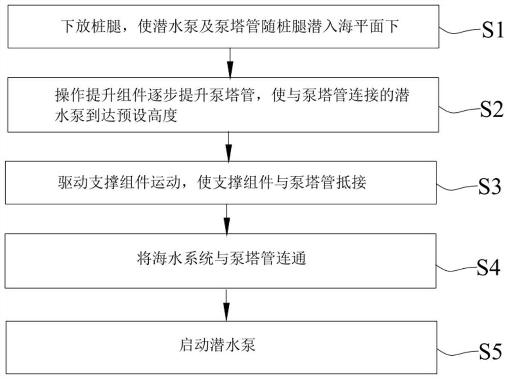
[0063] Embodiment of the present invention discloses a method of water offshore platforms, such as Figure 1 - Figure 12 As shown, the water offshore platform comprising the steps of:
[0064] Sl, decentralized legs, so that the submersible pump 22 and pipe 21 with the pump tower legs sneak below sea level;
[0065] S2, operation of the lift assembly 3 gradually increase the pump column pipe 21, so that the pump 21 submersible pump connected to the column tube 22 reaches a predetermined height;
[0066] S3, movement of the drive support assembly 4, the support assembly 4 and the column tube 21 abuts against the pump;
[0067] S4, the water pipe system in communication with the pump 21 column;
[0068] S5, start the submersible pump 22.
[0069] Thus, water offshore platform method of this embodiment, it is possible to achieve water offshore platform, a simple operation of the entire process water. The water offshore platform apparatus and a method comprising the following advantages: submersible pump 22 and a pump column pipe with legs 21 can dive into the sea, without additional lowering apparatus, simplifying the structure and operation; increased gradually by operating the third pump assembly lifting column tube 21, that the submersible pump connected to the column tube 21 of the pump 22 reaches a predetermined height, thereby achieving submersible pump 22 and a pump height adjustment column tube 21 to meet the water needs of different locations; a support assembly 4, the support column with the pump assembly 4 pipe 21 abuts, to achieve the stability limit of the pump tube support column 21, to improve the structure.
[0070] Hereinafter, the steps of the method of offshore platform abstraction particularly described.
[0071] Sl, decentralized legs, so that the submersible pump 22 and pipe 21 with the pump tower legs sneak below sea level.
[0072] Leg marine platform support portion, by the submersible pump 22 and a pump 21 is associated with the column tube legs, so that when decentralized legs, and can be realized decentralized pump 21 submersible pump column pipe 22, simplifying the structure and operation Process.
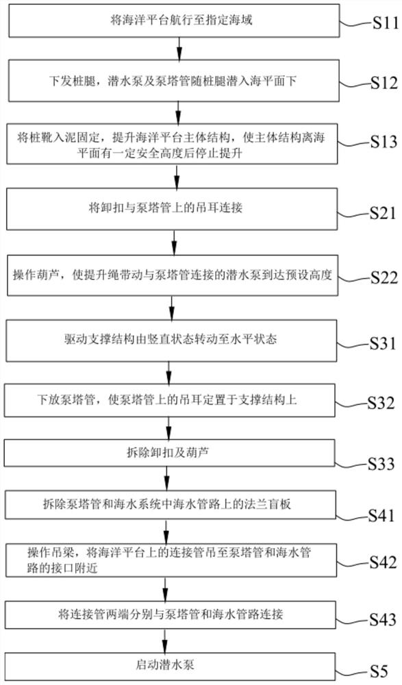
[0073] Specifically, steps S1 comprising:
[0074] S11, sailing the marine platform to the designated sea area;
[0075] S12, decentralization of legs, and a pump 22 submersible pump column pipe 21 with legs sneak below sea level;
[0076] S13, the pile shoe into the mud fixed offshore platform to enhance the main structure, the main structure height from sea level, there is a certain safety stop after the upgrade.
[0077] When sailing offshore platform to the designated area, the decentralization of the leg boots into the mud pile fixed to achieve the initial fixed for offshore platforms. Offshore platform structure to further enhance the body, the body structure has a certain safety height from the sea level to stop the lift, so as to facilitate marine operations. Meanwhile, the submersible pump 22 and a pump column pipe 21 with the legs sneak sea, without additional lowering apparatus, simplify the construction and operation.
[0078] S2, operation of the lift assembly 3 gradually increase the pump column pipe 21, so that a submersible pump connected to the pump 22 to the column tube 21 a predetermined height.
[0079] The pump assembly 3 by lifting the riser column 21 and submersible pump 22, enables the submersible pump 22 reaches a predetermined height of water, to meet the different needs of water. Incidentally, predetermined height of the submersible pump 22 safety distance from the seafloor, seabed mud entering the submersible pump to avoid damage to 22, for example, may be a predetermined height 4m-6m, according to the specific needs to be set according to the present embodiment is not particularly limited .
[0080] like Figure 5 - Figure 9 Shown, alternatively, the step S2 is lifting assembly 3 comprises a shackle 34, hoist 32 and the shackle 34 and the hoisting ropes 32 are connected to the hoist 33, further, comprising the step S2:
[0081] S21, the shackle 34 on the lugs 211 of the pump 21 is connected to the column tube;
[0082] S22, operation hoist 32, the lifting cord 33 and the pump drive column tube 21 connected to the submersible pump 22 reaches a predetermined height.
[0083] like image 3 with Figure 4 Shown, in this embodiment, the lugs 211 along the longitudinal direction of the tube pump tower 21 is provided with a plurality of spaced, shackle 34 which is selectively connected to a lug 211 on. Click, 32 by operating the hoist, the hoisting ropes 33 drives the pump column pipe 21 upward, when the lug 211 to be connected to the shackle 34 and the hoist 32 is high (i.e., the pump tube 21 can not lift the column node), detached shackles 34 so that shackle 34 211 is connected to a lower lug, lift pump 32 continues to operate hoist tower tube 21, in cycles, until the submersible pump 22 is stopped reaches a preset height.
[0084] S3, movement of the drive support assembly 4, the support assembly 4 and the column tube 21 abuts the pump.
[0085] By supporting the pump assembly 4 and the column tube 21 is brought into contact to achieve a fixed support for the column tube 21 of the pump, the pump to ensure the stability of the column tube 21.
[0086] like Figure 10 - Figure 11 Shown, further, the support assembly 4 includes a step S3 rotatable support structure 42, the step S3 comprises:
[0087] S31, drive support structure 42 is rotated by the vertical state to the horizontal state;
[0088] S32, decentralization of the pump column pipe 21, the pump column pipe 211 on the lugs 21 on a given support structure 42 is placed.
[0089] With this arrangement, lift pump 21 during column tube, the support structure 42 in a vertical state (stored state) to avoid hindrance to the motion of the pump column tube 21, when raised to a predetermined level of the pump tube column 21, the drive support structure 42 is rotated by the vertical state to the horizontal state (operation state), in order to achieve support for the column tube 21 of the pump.
[0090] Meanwhile, in this embodiment, in the process of lifting the pump column pipe 21, disassembly shackle 34 before, 21 is supported also by the drive support structure 42 to the pump column pipe, and further disassembly shackle 34 causes shackle 34 with the next suspended ear 211 is connected, and then hide the support structure 42 to operate the pump 32 continues to hoist tower lift tube 21, in order to achieve the role of supporting multiple support structure 42, is provided to reduce the equipment cost, adaptability.
[0091] Still further, after the step S32 further comprises:
[0092] S33, removal of the shackle 34 and hoist 32.
[0093] After the pump column tube 21 is fixed, the shackle 34 can be removed and other accessories hoist 32, re-use structure.
[0094] S4, the water pipe system 21 communicates with the pump column.
[0095] like Figure 12 As shown in, in particular, steps S4 comprising:
[0096] S41, removal of the pump 21 and column tube blank flange seawater system 6 on water conduit 213;
[0097] S42, the operation lifting beam 7, the connecting pipe 5 to the offshore crane tower near the interface 6 of the pump tube 21 and the water conduit;
[0098] S43, are connected to the connecting pipe 21 and pump tower water conduit 65 ends of the tube.
[0099] With this arrangement, the first tube 21 and the seawater pump tower water system pipe flange on the blind plate 6213 removed, and then the connecting pipe 5 to the vicinity of the interface pump tower crane tube 21 and water line 6, and then the connection pipe 5 both ends of the pump tube 21 and the water column 6 line connection, enabling the communication pipe 21 and the water pump tower conduit 6, to achieve water to provide water for the water system.
[0100] Play a role in connecting the connection pipe 5, which is suspended to the vicinity of the interface through which the lifting beam 7, and 21 to compensate for the distance between the sea water pump line 6 column tube. Further, both ends of the connecting pipe 5 are tightly connected to the pump column pipe flange interface 6, to ensure that the interface connector sealing flange 21 and the water line, while easy disassembly. Still further, as the hose connection pipe 5, to achieve a flexible connection.
[0101] S5, start the submersible pump 22.
[0102] After the connection is completed, start the submersible pump 22, the water passes through the pump column pipe 21 and the connecting pipe 5 into the water system on offshore platforms, systems and equipment for use on offshore platforms.
[0103] like Figure 3 - Figure 12 , The present embodiment also discloses a water offshore platform apparatus which employs the method described above water offshore platform, the apparatus comprises a solid water offshore platform pile frame 1, water 2 assembly, lifting assembly 3, and a support assembly 4 connecting pipe 5. Wherein the water pump tower assembly 2 comprises a tube 21 with the water conduit 21 can pump tower and a tube 21 connected to the submersible pump 22, the pump 21 and the column tube with the submersible pump 22 can sneak legs at sea level, a pump column pipe 6. Lifting assembly 3 is provided on a solid pile frame 1, the lift assembly 3 is connected to the pump column pipe 21, 22 for lifting the submersible pump to a predetermined height. 4 to the solid support assembly disposed on the pile frame 1, for supporting the tube pump tower 21. 5 and the connecting pipe 21 and the water pump column pipe line 6 is connected.
[0104] With this arrangement, you can achieve water offshore platform, the entire structure is compact, easy to operate.
[0105] like Figure 3 - Figure 5 Shown, further, a pump column pipe 21 is fixed along a vertical direction of the pile frame lifting, along the length direction of the host 211 is provided with a plurality of lugs, a plurality of spaced lugs 211. In particular, the bottom of each lug 211 has a slot 212 for the pump connected to the column tube 21 is fixed to the card.
[0106] like Figure 6 - Figure 8 , The lift assembly 3 is provided on top of a solid pile frame 1, the lift assembly 3 comprises a sliding lift frame 31, lift frame 31 includes a sliding strut 311, 312 and the slide beam seat slide beam 313, a solid pillar 311 provided on the pile frame the top strut 1 311 312 is fixedly connected to the sliding beam seat to the sliding beam seat 312 is stably supported, the slide beam 313 is slidably disposed on the seat 312 slide beam, sliding on the beam 313 provided in the lifting loop or lifting roller, in order to enhance the pump tower tube 21.
[0107] Further, the assembly 3 further comprises a lifting hoist 32, the hoisting ropes 33 and shackles 34, attached to the lift cord 33 through the lifting loops or lifting rollers 32 are connected by hoist ropes 33 and the lifting shackle 34, shackle 34 is removably wherein fixed to a lug 211, the pump can achieve lift tower 21 by operating the hoist tube 32. The specific operation is described in detail above, it is not repeated here.
[0108]Still further, the support assembly 4 is located beneath the lift assembly 3, the pump to the column tube 21 is supported. The support assembly 4 includes a rotary pin 41 and the support structure 42, support structure 4241 rotatably disposed on a solid carrier by rotation of the pile on the pin 1, pin 42 rotates the support structure 41 and support structure 42 can be brought into contact fixing lug 211 . With this arrangement, the support structure 42 can move along the rotating pin 41 (storage state) and the horizontal rotational state (operation state) in a vertical state between the support structure 42 and slots 212 abut fixed, thereby achieving the pump column pipe 21 support fixed. During operation of the support assembly 4 has been explained in the foregoing, is not repeated here.
[0109] like Figure 10 - Figure 12 As shown in this embodiment, the rotation pin 41 fixed to a solid on a support structure 42 and the rotation pin 41 rotatably connected to the pile frame, the support structure in order to achieve rotary connection 42. Of course, in other embodiments, the rotation pin 41 may be rotatably disposed on a support structure 42 is fixedly connected with the rotation pin 41 fixed pile frame, the support structure can be achieved in the rotary connection 42.
[0110] It will be appreciated that the rotation of the support structure 42 may also be provided by a manual drive or a motor driven cylinder, according to the specific needs to be set according to the present embodiment is not particularly limited.
[0111] 5 is a hose connection pipe, to achieve a flexible connection, bridge the gap 21 between the conduit 6 and the seawater pump column pipe. 5 through the connecting pipe to the lifting beam 7 lifting the pump 21 and the tower pipe 6 at the water line connection.
[0112] In summary, the present invention provides a method and apparatus for offshore platforms water, water comprising the steps of: decentralized legs, so that the submersible pump 22 and the pump tube 21 column with sneak legs at sea level; lifting operation gradually lift pump assembly 3 column tube 21, so that a submersible pump connected to the pump 22 to the column tube 21 a predetermined height; 4 motion drive support assembly, the support assembly 4 and the column tube 21 abuts the pump; seawater system communicating with the pump tube 21 column; start dive pump 22, in order to achieve water offshore platforms, water the whole process simple operation.
[0113] The water offshore platform apparatus and a method comprising the following advantages:
[0114] (1) submersible pump column pipe 22 and a pump 21 can dive into the sea with the legs, without additional lowering apparatus, simplifying the structure and operation;
[0115] (2) by operating the lifting assembly 3 gradually increase the pump column pipe 21, so that the pump column pipe 21 connected to the submersible pump 22 reaches a predetermined height, whereby height adjustment and a pump 22 submersible pump column pipe 21, to meet different locations water demand;
[0116] (3) a support assembly 4, the support assembly 4 and the column tube 21 abuts the pump, the pump to achieve the limit tube support column 21, to improve structural stability.
[0117] Obviously, the above-described embodiments of the present invention are merely illustrative of the embodiments of the invention, and is not limited to the embodiments of the present invention. For those skilled in the art, different variations or variations can also be made based on the above description. There is no need to be exhausted here. Any modification, equivalent replacement and improvement, etc. according to the spirit and principles of the present invention should be included within the scope of the claims.