
Low-carbon energy-saving building waterproof wall

A building waterproofing and wall technology, which is applied in the direction of buildings, building components, building structures, etc., can solve the problems that the insulation layer structure is not pressure-resistant, the filling is not ventilated, and the process is complicated and cumbersome, so as to achieve great promotion value and improve Practical value, the effect of improving durability

Inactive Publication Date: 2021-09-03
深圳市小红手科技有限公司
View PDF0 Cites 0 Cited by
  • Summary
  • Abstract
  • Description
  • Claims
  • Application Information

AI Technical Summary

Problems solved by technology

[0003] Existing building exterior walls generally include a decorative layer, waterproof layer, insulation layer, leveling layer, and exterior wall main body from the outside to the inside. In order to improve the construction speed and waterproof performance of the insulation layer, the existing exterior wall structure generally The insulation layer is sealed, this structure is easy to prevent the filling (rock wool) in the insulation layer from being ventilated, resulting in moisture accumulation
At the same time, the construction and installation process of the existing structure is also relatively complicated and cumbersome, especially the structure of the insulation layer is not pressure-resistant, and it is easy to be damaged during transportation and installation
The connection between the outer wall and the upper edge of the main body and the ground is poor, and water is easy to enter

Method used


Image

  • Low-carbon energy-saving building waterproof wall
  • Low-carbon energy-saving building waterproof wall
  • Low-carbon energy-saving building waterproof wall

Examples


Embodiment Construction

[0051] In order to make the above objects, features and advantages of the present invention more comprehensible, specific implementations of the present invention will be described in detail below in conjunction with the accompanying drawings. In the following description, numerous specific details are set forth in order to provide a thorough understanding of the present invention. However, the present invention can be implemented in many other ways different from this description, and those skilled in the art can make similar improvements without departing from the connotation of the present invention, so the present invention is not limited by the specific embodiments disclosed below.

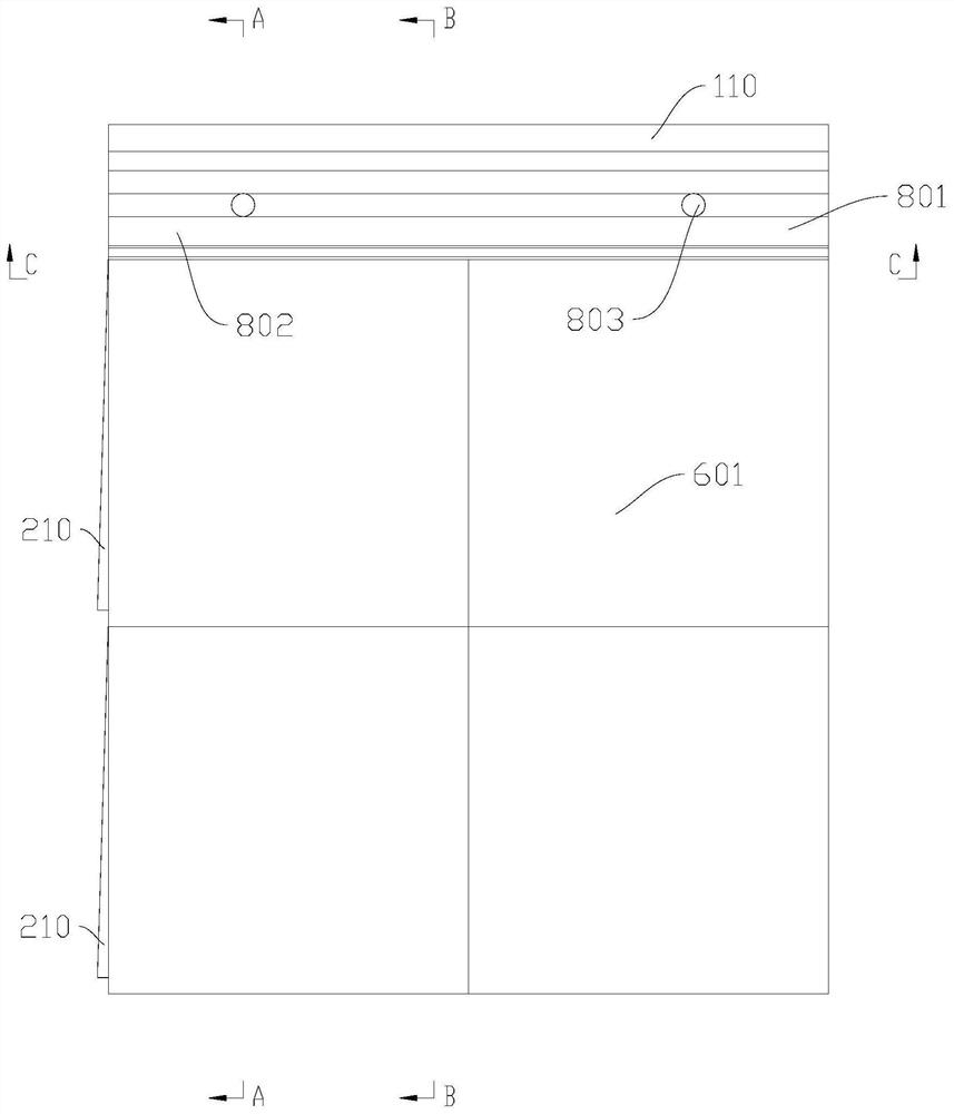
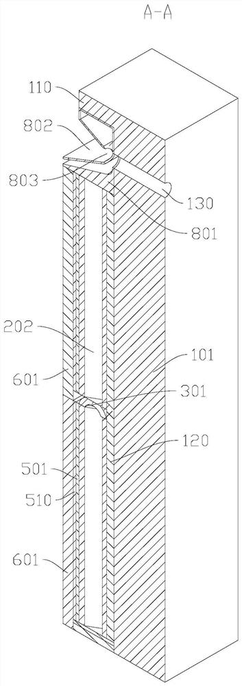
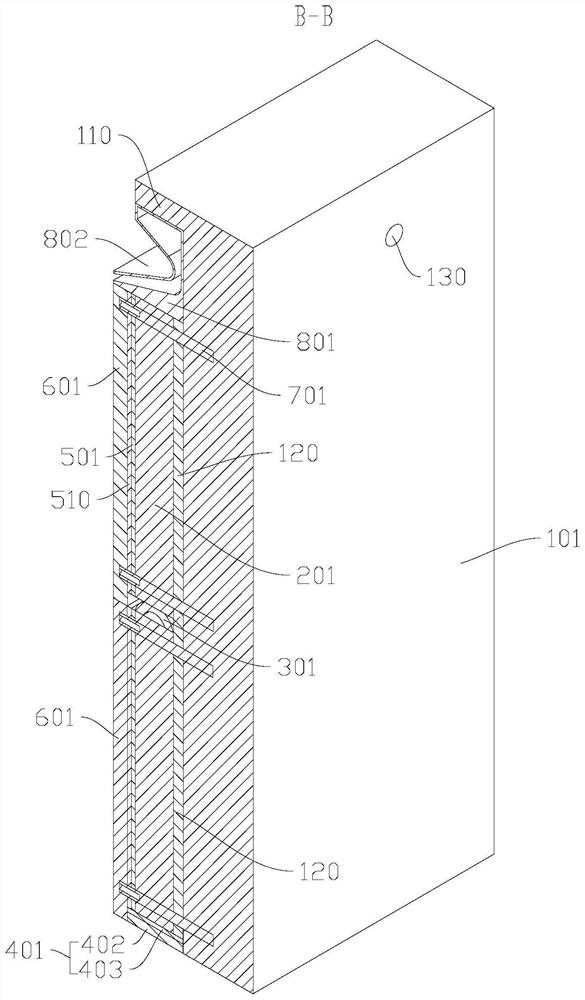
[0052] like Figure 1-Figure 5 As shown, the present invention discloses a low-carbon energy-saving building waterproof wall, comprising: a wall 101 and a leveling layer 120 laid on the surface of the wall 101, characterized in that the insulation layer 201, the insulation layer 201 is provid...


PUM


Abstract

The invention discloses a low-carbon energy-saving building waterproof wall. The low-carbon energy-saving building waterproof wall comprises a wall body, a leveling layer laid on the surface of the wall body, heat preservation layers, fixing bolts, waterproof layers, a decorative layer and a blocking piece, the heat preservation layers are provided with triangular through grooves penetrating through the upper face and the lower face, connecting clamping grooves are formed in the left sides of the heat preservation layers, connecting through grooves are formed in the right sides of the heat preservation layers, and the heat preservation layers are fixedly installed on a wall body; the heat preservation layers are fixedly installed on the wall body through the fixing bolts; the waterproof layers are brushed on the surfaces of the outer sides of the heat preservation layers; the decorative layer is fixedly installed on the fixing bolts, and the decorative layer is arranged on the outer side surfaces of the waterproof layers; and a ventilation groove is formed in the bottom face of the blocking piece, a material blocking plane is arranged on the top face of the blocking piece, and the blocking piece is installed between the heat preservation layers which are aligned up and down. The construction efficiency and the waterproofness of the outer wall heat preservation layers are improved, and meanwhile, the structure is stable and reliable.

Description

technical field [0001] The invention relates to the technical field of building exterior walls, in particular to a low-carbon energy-saving building waterproof wall. Background technique [0002] With the rapid development of urbanization, in order to respond to the policy and meet the needs of people's daily life, the construction of buildings is becoming more and more low-carbon, energy-saving, and efficient, forcing building exterior walls to multi-functional, integrated, stable, Design and build in the direction of convenience. [0003] Existing building exterior walls generally include a decorative layer, waterproof layer, insulation layer, leveling layer, and exterior wall main body from the outside to the inside. In order to improve the construction speed and waterproof performance of the insulation layer, the existing exterior wall structure generally The insulation layer is sealed, and this structure is easy to prevent the filling (rock wool) in the insulation laye...

Claims


Application Information

Patent Timeline
Patent Type & Authority Applications(China)
IPC IPC(8): E04B2/00E04B1/76E04B1/66
CPCE04B2/00E04B1/76E04B1/66
Inventor 黄雪燕黄金
Owner 深圳市小红手科技有限公司
Learn More