Urban highway environment-friendly construction device and construction method

A technology for construction devices and roads, applied in separation methods, chemical instruments and methods, cleaning methods, etc., can solve problems such as low construction efficiency, and achieve the effects of speeding up construction efficiency, convenient operation and good stability

Active Publication Date: 2021-09-03
廊坊市拓峰建设工程有限公司
View PDF20 Cites 1 Cited by
  • Summary
  • Abstract
  • Description
  • Claims
  • Application Information

AI Technical Summary

Problems solved by technology

[0003] At present, the connection between the water pipe and the color steel plate is mostly fixed by iron wire tightening, and the wat

Method used


Image

  • Urban highway environment-friendly construction device and construction method
  • Urban highway environment-friendly construction device and construction method
  • Urban highway environment-friendly construction device and construction method

Examples


Embodiment 1

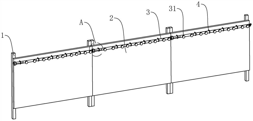
[0047] refer to figure 1 , There are several enclosures in the construction device. The enclosures are located in the highway construction area. The two adjacent enclosures are connected, so that the dust generated during the highway construction process is not easy to spread to the outside world, and the two adjacent enclosures can be removed. open to facilitate the construction and transfer of the enclosure.

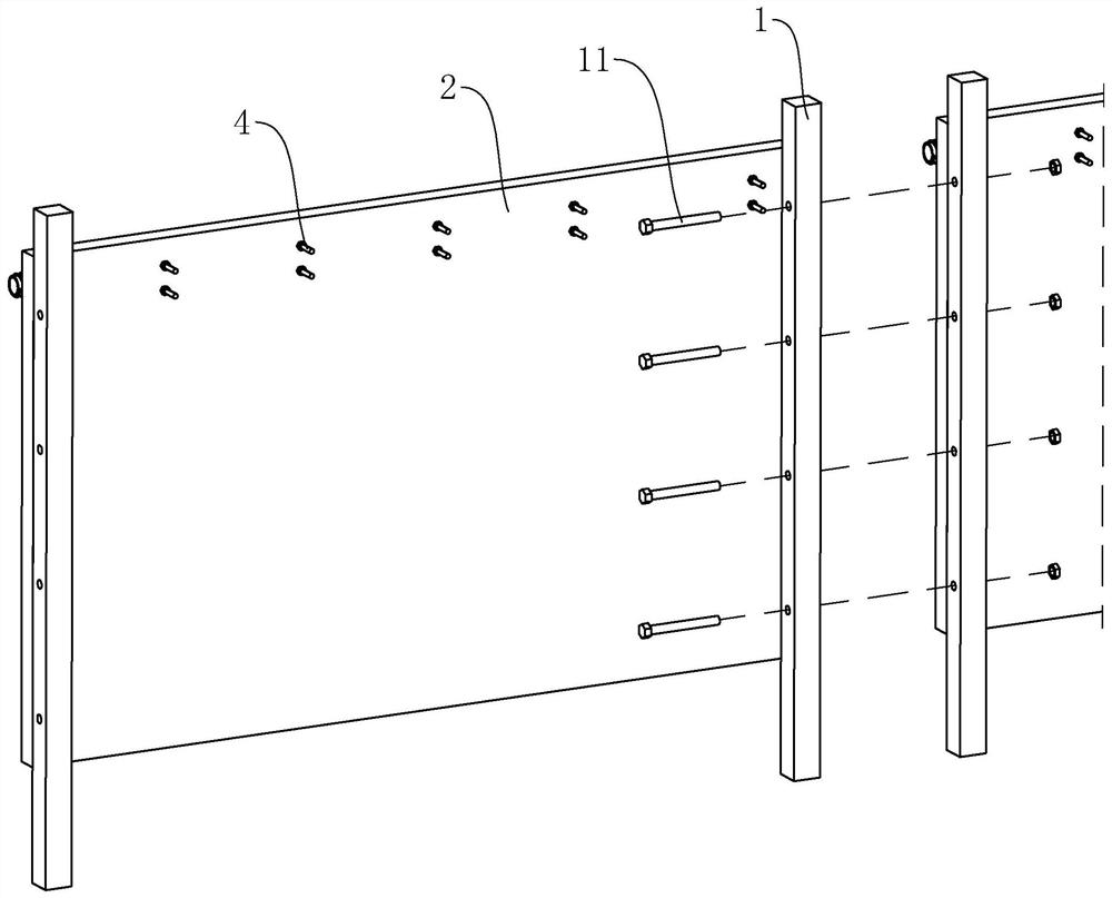
[0048] Among them, refer to figure 1 and figure 2 , the enclosure includes two columns 1 and baffles 2, the column 1 is a vertically placed rectangular column, the two columns 1 are spaced along the horizontal direction, the baffle 2 is a vertically placed flat plate, and the baffle 2 is in the horizontal direction The opposite ends are welded and fixed with the two uprights 1 respectively. The height of the bottom end of the column 1 is lower than the height of the bottom end of the baffle plate 2. The bottom end of the column 1 can be fixed on the ground on both ...

Embodiment 2

[0054] The difference between this embodiment and Embodiment 1 is that a telescopic member 7 is provided between the connecting pipe 5 and the conveying pipe 3 .

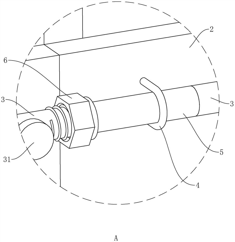
[0055] refer to Figure 5 , In this embodiment, a support ring 21 is fixed on the side wall of the baffle 2 away from the column 1, and the connecting pipe 5 is slidably connected to the support ring 21 through the support ring 21, so that the connecting pipe 5 can be connected to the baffle 2. Sliding along its own axis. The telescopic element 7 is connected between the conveying pipe 3 and the connecting pipe 5 , so that the connecting pipe 5 can maintain the state of communicating with the conveying pipe 3 when sliding.

[0056] In the process of building the enclosure, due to construction errors or processing errors, it is easy to cause the phenomenon that the distance between the connecting pipe 5 and the conveying pipe 3 in the two adjacent enclosures in the axial direction is too large or too small, which af...

Embodiment 3

[0063] The difference between this embodiment and the second embodiment is that the structure of the telescopic element 7 is different.

[0064] refer to Image 6 In this embodiment, the telescopic member 7 includes a moving pipe 72 and two hoses 71. The moving pipe 72 is located between the conveying pipe 3 and the connecting pipe 5. The axis of the moving pipe 72 is parallel to the axis of the conveying pipe 3. The moving pipe 72 The moving pipe 72 is a hard pipe supported by a PVC material or a metal material, and the moving pipe 72 is inserted into the slip ring 24 and is fixedly connected to the slip ring 24 . Two hoses 71 are sleeved and fixed on both ends of the moving pipe 72 respectively, one of the hoses 71 is sleeved and fixed on the conveying pipe 3 at the end of the hose 71 away from the moving pipe 72 , and the other hose 71 is away from the end of the moving pipe 72 . The sleeve is fixed on the connecting pipe 5 so as to connect the conveying pipe 3 with the co...


PUM


Abstract

The invention relates to an urban highway environment-friendly construction device and construction method, and belongs to the technical field of highway environment-friendly construction. The urban highway environment-friendly construction device comprises a plurality of fences used for being arranged in a highway construction area in a surrounding mode, and every two adjacent fences are spliced together; each fence comprises a baffle, a conveying pipe fixedly arranged at the top of the baffle, a plurality of spray heads fixed to and communicating with the conveying pipe, a connecting pipe arranged on the baffle and communicating with one end of the conveying pipe, and a movable joint arranged at the end, away from the conveying pipe, of the connecting pipe; and in every two adjacent fences, the two baffles are detachably fixed together, and the connecting pipe in one fence and the conveying pipe in the other fence are fixed and communicate through the movable joint. When the fences are built, all the conveying pipes can rapidly communicate together in the building process of the fences through matched connection among the movable joints, the connecting pipes and the conveying pipes, so that water spraying and dust suppression are conveniently carried out in the highway construction process, and the construction efficiency of assembling and disassembling the fence is improved.

Description

technical field [0001] The application relates to the field of road environmental protection construction, in particular to an urban road environmental protection construction device and construction method. Background technique [0002] In the process of maintenance, reconstruction or new construction of roads in the urban area, color steel plate retaining walls are usually temporarily built on both sides of the construction road to separate the construction area from the non-construction area, which can block the flying noise generated during the construction process. In addition, a water pipe will be fixed on the inner side of the color steel plate retaining wall. At the same time, a nozzle will be installed on the water pipe. During the construction process, water will be passed into the water pipe, so that the nozzle will spray water mist into the air above the construction area to further suppress The emission of dust to the outside world achieves the purpose of enviro...

Claims


Application Information

Patent Timeline
IPC IPC(8): E04H17/16E01H3/04B01D47/06
CPCE04H17/16E01H3/04B01D47/06
Inventor 李占赵志一张孟冬郭广生张营营马宏伟张兵胡涛王磊何煦
Owner 廊坊市拓峰建设工程有限公司
Why Eureka
Try Eureka