Tunnel pipe shed dismantling device in foundation pit range

A tunnel pipe and scope technology, applied in the direction of tunnels, tunnel linings, mining equipment, etc., can solve the problems of unfavorable motors working for a long time, inability to protect the motor from heat dissipation, and reduce the efficiency of disassembly, so as to improve the efficiency of demolition, realize protection, reduce effect of labor

Pending Publication Date: 2021-09-03
李志强
View PDF5 Cites 0 Cited by
  • Summary
  • Abstract
  • Description
  • Claims
  • Application Information

AI Technical Summary

Problems solved by technology

[0005] The disadvantage of the above-mentioned patent documents is that when removing another pipeline, it needs to ensure that it is directly opposite to the pipeline, whether in the horizontal or vertical direction, otherwise it cannot be accurately snapped into the corresponding position, and it is inconvenient to proceed. dismantling; and the above-mentioned patent documents have no corresponding mechanism to ensure that the horizontal and vertical directions are opposite, so that multiple adjustments are required, thereby reducing the efficiency of disassembly; at the same time, the motor cannot be effectively protected from heat dissipation, which is not conducive to the long-term operation of the motor. Time works, so we designed a tunnel pipe shed removal device within the scope of the foundation pit to solve the above problems

Method used


Image

  • Tunnel pipe shed dismantling device in foundation pit range
  • Tunnel pipe shed dismantling device in foundation pit range
  • Tunnel pipe shed dismantling device in foundation pit range

Examples


Embodiment Construction

[0027] The following will clearly and completely describe the technical solutions in the embodiments of the present invention with reference to the accompanying drawings in the embodiments of the present invention. Obviously, the described embodiments are only some, not all, embodiments of the present invention.

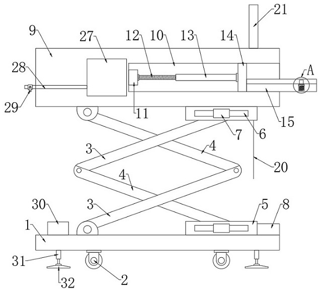
[0028] refer to Figure 1-4 , a tunnel pipe shed demolition device within the scope of the foundation pit, including a base 1, four universal wheels 2 and four supporting mechanisms are fixedly connected to the bottom of the base 1, and the supporting mechanism includes an electric telescopic rod 31 fixed on the bottom of the base 1 , the output end of the electric telescopic rod 31 is fixedly connected with a support plate 32, and the electric telescopic rod 31 drives the support plate 32 to move downward to offset against the ground, so that the base 1 can be stably supported, thereby ensuring the stability of the base 1.

[0029] A lifting plate 9 is provided abov...


PUM


Abstract

The invention discloses a tunnel pipe shed dismantling device in a foundation pit range. The tunnel pipe shed dismantling device in the foundation pit range comprises a base, wherein four universal wheels and four supporting mechanisms are fixedly connected to the bottom of the base, a lifting plate is arranged above the base, a lifting mechanism is arranged between the lifting plate and the base, an accommodating groove is formed in one side of the lifting plate, a driving motor is installed in the accommodating groove, the output end of the driving motor is fixedly connected with a reciprocating lead screw, the reciprocating lead screw is sleeved with a sleeve matched with the reciprocating lead screw, and a rectangular block is slidably connected into the accommodating groove. According to the tunnel pipe shed dismantling device, it can be guaranteed that a pipeline is right opposite to an arc-shaped plate, then it can be guaranteed that a limiting column can be clamped into a drilled hole, repeated adjustment is not needed, the pipeline dismounting efficiency can be improved, meanwhile, workers do not need to move equipment for multiple times, the labor amount of the workers is greatly reduced, meanwhile, the driving motor can be cooled, and therefore, the drive motor is protected.

Description

technical field [0001] The invention relates to the technical field of tunnel construction, in particular to a tunnel pipe shed removal device within the range of a foundation pit. Background technique [0002] Tunnel pipe shed, pipe shed advanced support method is a new technology developed in recent years for tunnel excavation in weak surrounding rock. The pipe shed method was first used as an auxiliary method for tunnel construction. It played an important role in the construction of soft rock tunnels through broken zones, loose zones, and weak strata, and water and sand gushes. Because the pre-buried advanced tube shed is used as roof and side wall support. It has laid a solid foundation for subsequent tunnel excavation, and has fast construction, high safety and short construction period. It is considered to be the most effective and reasonable construction method to solve the risky item in tunnel construction. Pipe shed construction The pipe shed is to use the steel...

Claims


Application Information

Patent Timeline
IPC IPC(8): E21D11/15E21F17/00
CPCE21D11/152E21F17/00
Inventor 李志强
Owner 李志强
Why Eureka
Try Eureka