Device for pumping polyphenyl granule slurry

A technology of slurry and material cylinder, which is applied in the field of construction engineering pumping devices, can solve the problems of low pumping speed, change of slurry bulk density, and short service life of screws, etc., and achieve high pumping efficiency, improved efficiency, and improved work efficiency and the effect of service life

Pending Publication Date: 2021-09-03
李江安
View PDF1 Cites 0 Cited by
  • Summary
  • Abstract
  • Description
  • Claims
  • Application Information

AI Technical Summary

Problems solved by technology

It not only changes the properties of the slurry, but also changes the bulk density of the slurry, which canno

Method used


Image

  • Device for pumping polyphenyl granule slurry
  • Device for pumping polyphenyl granule slurry
  • Device for pumping polyphenyl granule slurry

Examples


Example Embodiment

[0036] Specific implementation one:

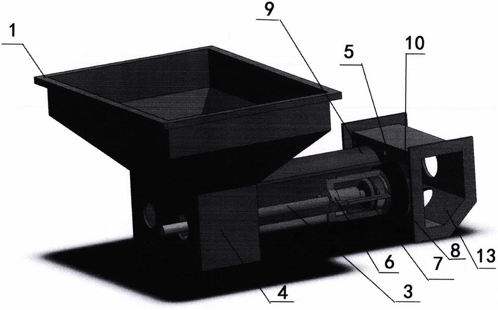
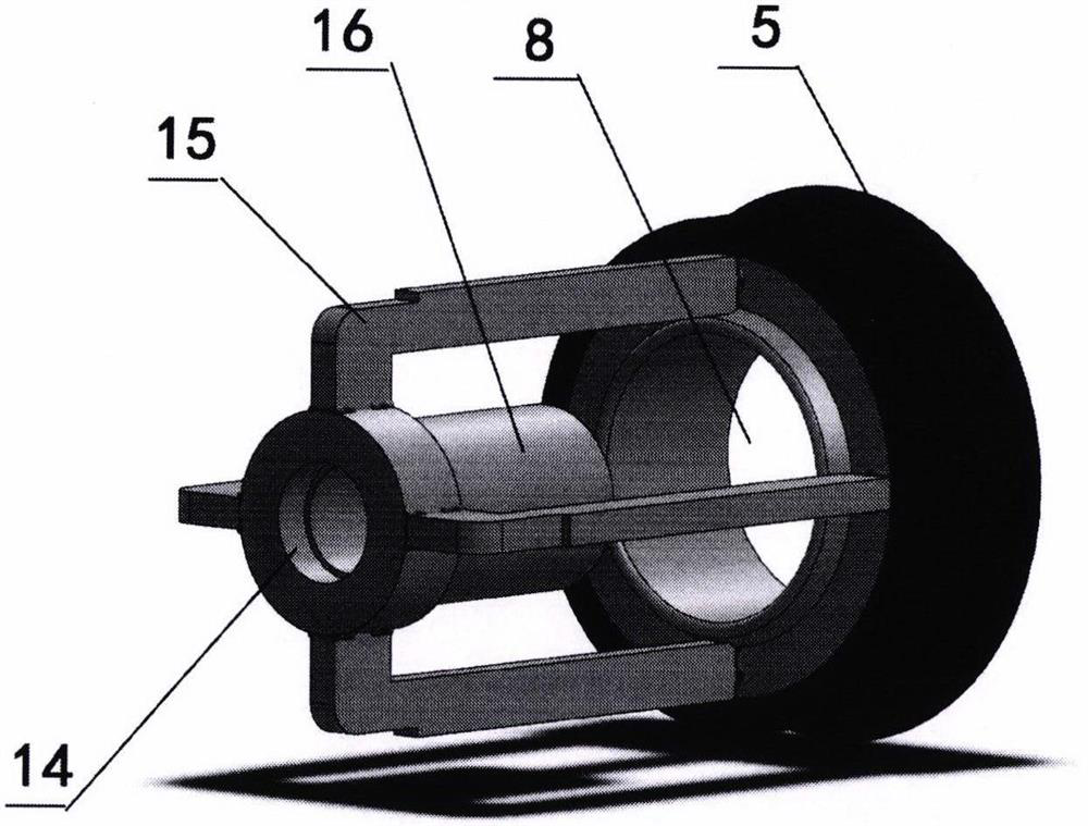
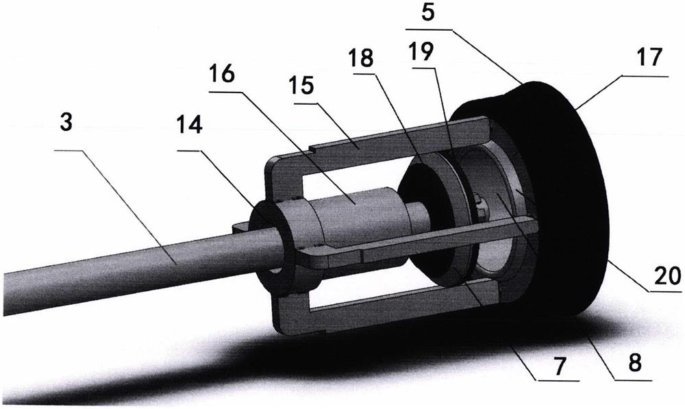
[0037] see figure 1 , 4 , 5, the device for pumping the polystyrene particle slurry according to the present invention includes: a hopper 1, a hydraulic cylinder (not shown in the figure), a hydraulic cylinder shaft 3 (also called a push rod 3), a feeding bin 4, a piston body 5. Piston tail pipe 6, feed port cover 7, feed port 8, material cylinder 9, discharge port 10, discharge port cover 11, conveying pipe connection port 12, discharge bin 13. Among them, the hydraulic cylinder 2, the discharge port cover 11, the conveying pipe connection port 12, and the discharge bin 13 are in figure 1 not visible in, see Figure 4 or Figure 5 . The hopper 1 is arranged above the feeding bin 4 and communicates with the feeding bin 4. Two through holes are provided on the left side wall of the bin 4 for the hydraulic cylinder shaft to pass through. The hydraulic cylinder 2 is fixedly installed on the left side of the feeding bin 4. on the wall. ...

Example Embodiment

[0047] Specific implementation two:

[0048] The difference between the second embodiment according to the present invention and the first embodiment above is that the discharge port covers of the two are different, and the rest of the structures are the same.

[0049] see Figure 8 , In the second embodiment, the second discharge port cover 31 can reciprocate left and right along the axial direction of the discharge port cover shaft 27. When the second discharge port cover 31 presses the discharge port 10, the second discharge port The cover 31 can close the discharge port 10 , and the second discharge port cover 31 can be a multi-layer structure, wherein the side close to the discharge port 10 is provided with an elastic sealing layer. The second discharge port cover 31 is supported by the discharge port cover shaft 27. The discharge port cover shaft 27 passes through the inside of the discharge port cover guide block 30. The discharge port cover guide block 30 has the left...


PUM


Abstract

The invention relates to a device for pumping polyphenyl granule slurry. A piston is connected with a hydraulic cylinder shaft through a piston tail pipe and a feeding port cover, when a hydraulic cylinder is in a push-out state, the piston is pushed to move synchronously by utilizing the relation that the feeding port cover is larger than a feeding port, and when the hydraulic cylinder retracts, similarly, by utilizing the relation that the size of the feeding port cover is larger than the inner diameter of a center pipe of the piston tail pipe, the piston is pushed to move when the feeding port cover moves to the center pipe of the piston tail pipe, so that the slurry is continuously pumped through reciprocating motion of the hydraulic cylinder. The device cannot influence the characters of polyphenyl granules and foamed cement in the working process, and has high pumping efficiency; and the device does not comprise obviously quick-wear parts, so that the working efficiency is greatly improved, and the service life is greatly prolonged.

Description

technical field [0001] The invention relates to a slurry pumping device, in particular to a pumping device for polystyrene granular aggregate and foamed cement mixture, and belongs to the field of construction engineering pumping devices. Background technique [0002] At present, there is no professional pumping equipment for polyphenylene particles and foamed cement mixture on the market. The mortar spraying machine used for pumping polyphenylene particles and foamed cement mixture is used instead. As we all know, the mortar spraying machine The working principle is to use the spiral rolling method to send the slurry under high pressure. There is no problem with this equipment extruding the sand slurry, but it is not suitable for the mixture of polyphenylene particles and foamed cement. [0003] Chinese utility model patent CN202357286U discloses a composite foam concrete batching mixing and pumping equipment, including a base, a stirring shell is arranged on the base, a fe...

Claims


Application Information

Patent Timeline
IPC IPC(8): F04B15/02F04B9/10F04B53/00F04B53/16
CPCF04B15/02F04B9/10F04B53/00F04B53/16
Inventor 李江安
Owner 李江安
Why Eureka
Try Eureka