
Fan assembly and air conditioner indoor unit

A technology for indoor units and fan components of air conditioners, which is applied to air conditioning systems, machines/engines, pump components, etc., and can solve problems such as unsatisfactory overall appearance, high working noise, and small air volume

Pending Publication Date: 2021-09-03
许彐琼
View PDF1 Cites 0 Cited by
  • Summary
  • Abstract
  • Description
  • Claims
  • Application Information

AI Technical Summary

Problems solved by technology

The air conditioning device with this structure has a small output air volume and high working noise, and its overall appearance cannot meet people's needs.

Method used


Image

  • Fan assembly and air conditioner indoor unit
  • Fan assembly and air conditioner indoor unit
  • Fan assembly and air conditioner indoor unit

Examples


Embodiment Construction

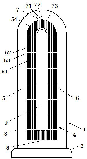
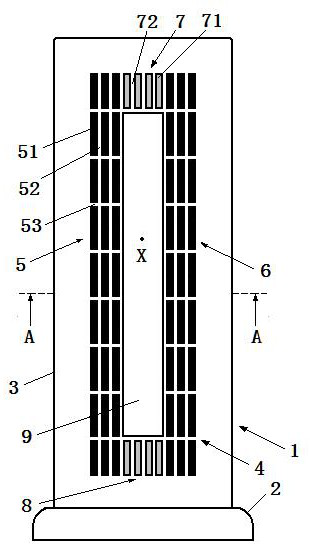
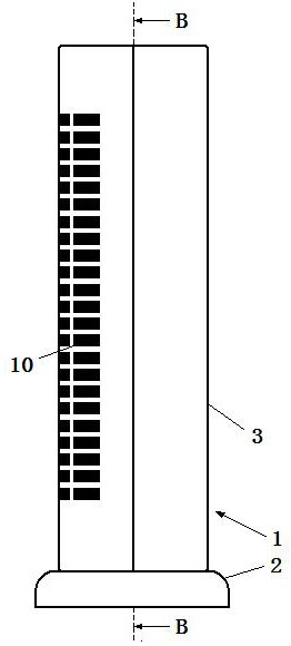
[0047] Figure 1 is a schematic view of the fan assembly of the present invention viewed from the front of the fan assembly, figure 2 is a side view of the fan assembly shown in Figure 1, image 3 is along figure 1 The cross-sectional view of the fan assembly taken by the line A-A in Figure 4 is along figure 2 The cross-sectional view of the fan assembly taken by the line B-B in . From Figure 1 to Figure 4 As can be seen from the figure, the fan assembly of the present invention includes a base 2 and a body 1 arranged on the base 2, the body 1 includes a casing 3, a first driving motor 17 located in the casing 3, a second driving motor 18, The first cross-flow impeller 11 and the second cross-flow impeller 12 .

[0048] In this embodiment, both the first driving motor 17 and the second driving motor 18 are DC brushless motors, and the first driving motor 17 and the second driving motor 18 drive the first cross-flow impeller 11 and the second cross-flow impeller 12 respe...


PUM


Abstract

The invention discloses a fan assembly and an air conditioner indoor unit. The fan assembly comprises a shell, a first cross-flow impeller and a second cross-flow impeller, the first cross-flow impeller and the second cross-flow impeller are located in the shell, a through hole is defined in the shell. The fan assembly is characterized by comprising a grating arranged on the shell, the grating includes a first air outlet grating portion, a second air outlet grating portion and a first non-air outlet grating portion, the first non-air outlet grating portion is connected with the upper portion of the first air outlet grating portion and the upper portion of the second air outlet grating portion respectively. According to fan assembly and the air conditioner indoor unit, the fan assembly can provide airflow with large wind volume and low noise, and has the advantages of being good in overall appearance and easy to produce.

Description

technical field [0001] The invention relates to the technical field of air conditioning, and more specifically relates to a fan assembly and an indoor unit of an air conditioner. Background technique [0002] The Chinese patent application with patent publication number CN104165134A on November 26, 2014 (application number: 201310186724.5) discloses an air conditioning device, which includes: a base and a nozzle installed on the base, the The base includes an outer housing with side walls, an impeller housing with an air inlet and an air outlet inside the housing, an impeller with an air inlet and an air outlet inside the housing, and a motor that drives the impeller to rotate about an axis, the side walls including At least one air inlet, the nozzle including an internal passage for receiving airflow from the base and a mouth, wherein the airflow exits through the mouth. The air-conditioning device with this structure has a small output air volume and high operating noise,...

Claims


Application Information

Patent Timeline
IPC IPC(8): F24F1/0025F24F13/28F24F13/24F04D25/08F04D29/70F04D29/66
CPCF24F1/0025F24F13/28F24F13/24F04D25/08F04D29/70F04D29/66
Inventor 任文华
Owner 许彐琼
Learn More