
Heat dissipation module, electric appliance heat dissipation assembly and air conditioner

A heat dissipation module and heat dissipation component technology, which is applied in air conditioning systems, household heating, heating methods, etc., can solve the problems of condensed water, power consumption of components and easy burning, and achieve the effect of avoiding high temperature phenomena

Active Publication Date: 2021-09-03
QINGDAO HISENSE HITACHI AIR CONDITIONING SYST
View PDF5 Cites 0 Cited by
  • Summary
  • Abstract
  • Description
  • Claims
  • Application Information

AI Technical Summary

Problems solved by technology

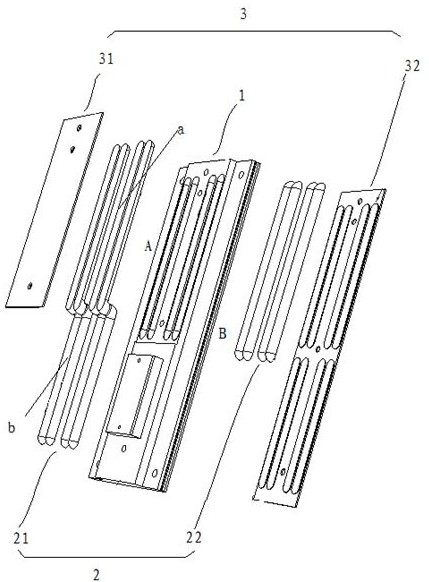
[0005] In order to solve the problems in the existing refrigerant heat dissipation scheme that the components are easy to be burned when the power consumption is large, and condensation water will be generated when the temperature of the components is below the dew point, the present invention proposes a heat dissipation module, an electrical heat dissipation component and an air conditioner, Combined with refrigerant heat dissipation and phase change structure to control thermal resistance, to ensure that the temperature of components always meets the design requirements, without adding control devices, which improves the reliability of refrigerant heat dissipation

Method used


Image

  • Heat dissipation module, electric appliance heat dissipation assembly and air conditioner
  • Heat dissipation module, electric appliance heat dissipation assembly and air conditioner
  • Heat dissipation module, electric appliance heat dissipation assembly and air conditioner

Examples


Embodiment Construction

[0019] The following will clearly and completely describe the technical solutions in the embodiments of the present invention with reference to the accompanying drawings in the embodiments of the present invention. Obviously, the described embodiments are only some, not all, embodiments of the present invention. Based on the embodiments of the present invention, all other embodiments obtained by persons of ordinary skill in the art without making creative efforts belong to the protection scope of the present invention.

[0020] In describing the present invention, it is to be understood that the terms "center", "upper", "lower", "front", "rear", "left", "right", "vertical", "horizontal", The orientations or positional relationships indicated by "top", "bottom", "inner", "outer", etc. are based on the orientations or positional relationships shown in the drawings, and are only for the convenience of describing the present invention and simplifying the description, rather than in...


PUM


Abstract

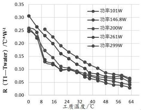
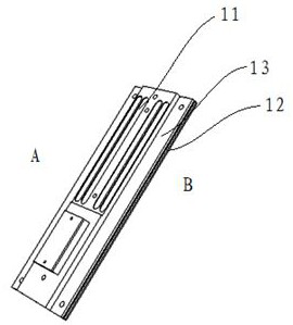
The invention discloses a heat dissipation module, an electric appliance heat dissipation assembly and an air conditioner. The heat dissipation module is composed of a fixing plate, a multiphase heat transfer assembly and a packaging layer. A first multiphase heat transfer piece is bent to form an evaporation section and a condensation section, and the evaporation section and the condensation section are fixed to the fixing plate in a penetrating mode, so that the evaporation section and the condensation section are attached to the two side faces of the fixing plate correspondingly. A second multiphase heat transfer piece is fixed on the second side surface of the fixing plate and is arranged opposite to the evaporation section. When the heat dissipation module is applied to heat dissipation, an evaporation side is connected with a power element, heat dissipated by the power element enables the temperature of the evaporation section to rise, the temperature of the initial condensation section is low, the heat resistance of the multiphase heat transfer assembly is large, the heat transfer efficiency is low, the temperature can be controlled above the dew point temperature, and condensed water is avoided. As the temperature rises, the heat resistance of the multiphase heat transfer assembly is reduced, and the multiphase heat transfer assembly and the fixing plate transfer heat simultaneously, so that it is effectively ensured that the heat of the power element is quickly dissipated, it is ensured that the temperature of the power element meets the design requirement all the time, and the reliability of a refrigerant heat dissipation mode is improved.

Description

technical field [0001] The invention relates to the technical field of electrical heat dissipation, in particular to a heat dissipation module, an electrical heat dissipation component and an air conditioner. Background technique [0002] As an important feature to measure the life of components, temperature rise plays an important role in the design of electronic products. The heat dissipation of the electrical box in the prior art mostly adopts two ways of forced air cooling and refrigerant heat dissipation. [0003] Among them, air-cooled heat dissipation has a simple structure, low cost, and stable and reliable performance. However, with the continuous development of component integration, power consumption has increased significantly, and air-cooled heat dissipation can no longer meet the temperature rise and life requirements of electrical boxes. At the same time, efficient and reliable air-cooled Road design will also be limited by space. The principle of the refrig...

Claims


Application Information

Patent Timeline
Patent Type & Authority Applications(China)
IPC IPC(8): F24F1/0063F24F13/22F24F13/30
CPCF24F1/0063F24F13/30F24F13/222
Inventor 史新清何成军绳燕
Owner QINGDAO HISENSE HITACHI AIR CONDITIONING SYST
Learn More