Intelligent industrial automatic control instrument system and control method thereof

An instrument system and control method technology, applied in the direction of instruments, force/torque/power measuring instruments, measuring devices, etc., can solve the problems of difficult to complete the adjustment work, difficult to control the preset value, etc., to achieve the use convenient effect

Pending Publication Date: 2021-09-03
泉州飞飞酷酷网络科技有限公司
View PDF1 Cites 1 Cited by
  • Summary
  • Abstract
  • Description
  • Claims
  • Application Information

AI Technical Summary

Problems solved by technology

[0005] Aiming at the deficiencies of the prior art, the present invention provides an intelligent industrial automatic control instrument system and its control method, which solves the problem that the distance between two packaged objects, the weight of the object and the shape of the object will correspond to two different power rollers. The distance between the preset values ​​is difficult to control, and the adjustment work is difficult to complete well.

Method used


Image

  • Intelligent industrial automatic control instrument system and control method thereof
  • Intelligent industrial automatic control instrument system and control method thereof
  • Intelligent industrial automatic control instrument system and control method thereof

Examples


Embodiment 1

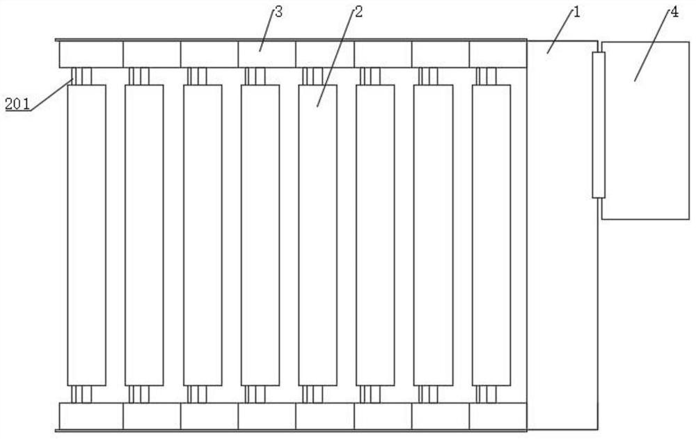
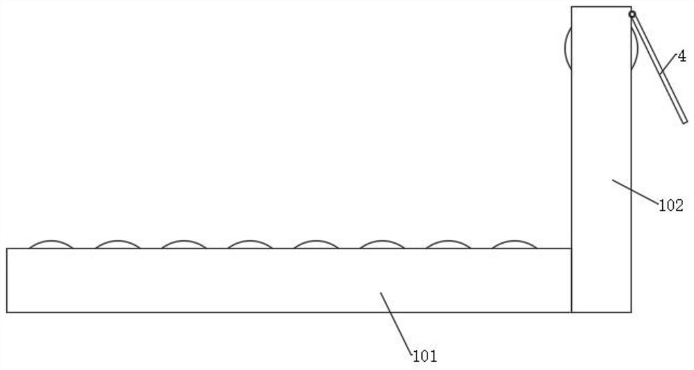
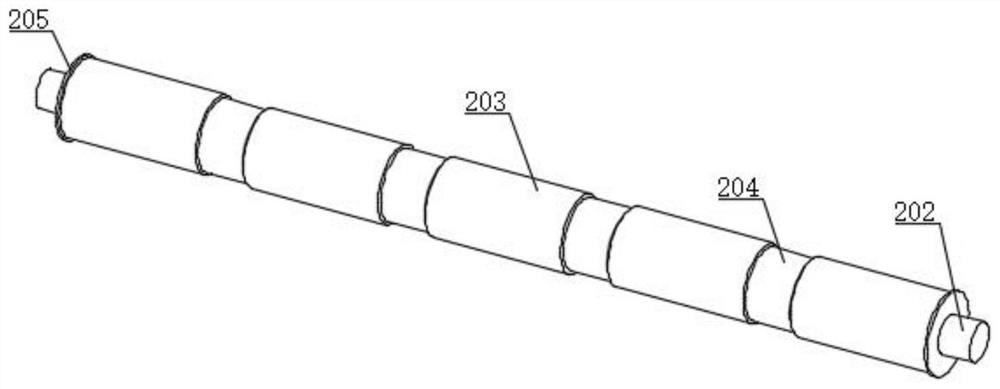
[0036] Such as Figure 1-5 As shown, the embodiment of the present invention provides an intelligent industrial automatic control instrument system, including a transmission frame 1, two rows of roller shaft mounting seats 3 are symmetrically arranged on the inner side of the transmission frame 1, and the roller shaft mounting seats 3 correspond to each other A power roller 2 is connected between the two corresponding roller shaft mounts 3, and a pressure detection ring 204 is arranged on the side of the power roller 2, and the pressure detection ring 204 detects the centrifugal force received by itself, its own gravity, The impact force and bearing capacity received, the annular structure can detect the force received by the power roller 2 for a week, the roller shaft mounting seat 3 is slidingly connected to the transmission frame 1, and the roller shaft mounting seat 3 and the transmission frame 1 are arranged There is a mechanism for adjusting the sliding of the roller sha...

Embodiment 2

[0043]An embodiment of the present invention provides a control method for an intelligent industrial automatic control instrument system, comprising the following steps:

[0044] Step 1. The user now sets the distance between two adjacent power rollers 2 according to the usage requirements, and then conducts preliminary operation and debugging;

[0045] Step 2: Place the product on the power roller 2, and then the power roller 2 rotates to drive the product to move, and is transported from the previous power roller 2 to the next power roller 2, and the pressure detection ring 204 detects that the latter power roller 2 first contacts the product Stress points;

[0046] Step 3, reflect whether the distance between two adjacent power rollers 2 meets the transportation requirements of the product according to the force point;

[0047] Step 4: Control the extension of the pneumatic telescopic part 104 to make the sliding block 301 in a slidable state, control the rotation of the a...

Embodiment 3

[0049] refer to Figure 5 An embodiment of the present invention provides a control method for an intelligent industrial automatic control instrument system further comprising:

[0050] Determine the position of point A, which is the position of the highest point of the power roller 2;


PUM


Abstract

The invention provides an intelligent industrial automatic control instrument system and a control method thereof, which relate to the technical field of industrial automatic transportation. The intelligent industrial automatic control instrument system comprises a conveying frame, two rows of roller shaft mounting seats are symmetrically arranged on the inner side of the conveying frame, a power roller is connected between the two corresponding roller shaft mounting seats, a pressure detection ring is arranged on the side face of the power roller, an instrument panel body is connected to the top of a vertical frame through a hinge, and the instrument panel body is electrically connected with the pressure detection ring and used for detecting whether the distance between the power rollers is appropriate or not. Through the arrangement of the pressure detection ring structure, the distance between the two power rollers is detected when an object is conveyed on the power rollers, the distance is judged to be proper, large or small, then the position of the roller shaft mounting seat is adjusted through the adjusting wheel structure, and then the positions of the power rollers are adjusted. Therefore, objects can be transported in a labor-saving and safe mode, impact on the power roller is avoided, and the service life of the power roller is not affected.

Description

technical field [0001] The invention relates to the technical field of industrial automation transportation, in particular to an intelligent industrial automatic control instrument system and a control method thereof. Background technique [0002] With the rapid development of industrial technology, the transmission and transfer of items is separated from manual handling, and more and more places use automated assembly line transportation. The traditional roller conveyor has a simple structure, and it is very easy to adjust the distance between two adjacent power rollers. Difficult, for conveying different materials, the distance between the two power rollers required is also difficult to determine. [0003] When the applicant applied for the present invention, after searching, it was found that the Chinese patent disclosed "an intelligent industrial automatic control instrument system and its control method", and its application number is "201911270646.0". Cleaning is carr...

Claims


Application Information

Patent Timeline
Patent Type & Authority Applications(China)
IPC IPC(8): G01L5/00B65G13/06
CPCG01L5/00B65G13/06
Inventor 邹巧凤
Owner 泉州飞飞酷酷网络科技有限公司
Why Eureka
Try Eureka