
Polarization maintaining optical fiber coupling type electro-optical crystal electric field sensor

A technology of electric field sensors and polarization-maintaining optical fibers, which is applied in the fields of electromagnetic field characteristics, instruments, and measurement of electrical variables. It can solve problems such as high optical path coupling loss, limited sensor structure compactness, and complicated setting of optical path static working points to achieve transmission efficiency. The effect of improving and simplifying the design structure

Pending Publication Date: 2021-09-03
KUNMING UNIV OF SCI & TECH
View PDF0 Cites 0 Cited by
  • Summary
  • Abstract
  • Description
  • Claims
  • Application Information

AI Technical Summary

Problems solved by technology

The separation of optical components such as polarizers and 1 / 4 wave plates in the sensing unit makes the setting of the static working point of the optical path complicated, and the coupling loss of the optical path is high, which limits the compactness of the sensor

Method used


Image

  • Polarization maintaining optical fiber coupling type electro-optical crystal electric field sensor
  • Polarization maintaining optical fiber coupling type electro-optical crystal electric field sensor
  • Polarization maintaining optical fiber coupling type electro-optical crystal electric field sensor

Examples


Embodiment Construction

[0041] Next, the technical solutions in the embodiments of the present invention will be apparent from the embodiment of the present invention, and it is clearly described, and it is understood that the described embodiments are merely embodiments of the present invention, not all of the embodiments. Based on the embodiments of the present invention, there are all other embodiments obtained without making creative labor without making creative labor premises.

[0042] In order to make the above objects, features, and advantages of the present invention, the present invention will be further described in detail below with reference to the accompanying drawings and specific embodiments.

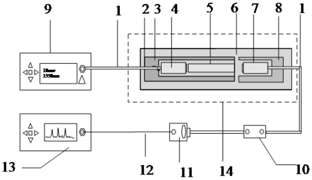
[0043] like figure 1 As shown, the present invention provides a polarized fiber coupled type electro-optical crystal electric field sensor, including an adjustable harmonic light source 9, one oscilloscope 13, a polarizing fiber 1, a pair of polarized fiber collimators, a tantalum Satium-acid cryst...


PUM

PropertyMeasurementUnit
sizeaaaaaaaaaa

Abstract

The invention discloses a polarization maintaining optical fiber coupling type electro-optical crystal electric field sensor. The sensor comprises an input end packaging base, an input polarization maintaining optical fiber collimator, an electro-optical crystal, a packaging shell, an output polarization-maintaining optical fiber collimator and an output end packaging base. The output end face of the input polarization maintaining optical fiber collimator is parallel to the light passing face of the electro-optical crystal. The electro-optical crystal is located between the input polarization-maintaining optical fiber collimator and the output polarization-maintaining optical fiber collimator, and the output polarization-maintaining optical fiber collimator and the input polarization-maintaining optical fiber collimator are coaxially arranged; the input end packaging base and the output end packaging base are both fixed on the packaging shell; and the polarization maintaining optical fiber is coupled with the input polarization-maintaining optical fiber collimator and the output polarization-maintaining optical fiber collimator respectively. According to the invention, the arrangement problem of a quiescent working point is solved by using the torsion of the polarization maintaining optical fiber, and the use of 1 / 4 wave plates is reduced; and through direct coupling of the polarization maintaining optical fiber, the transmission efficiency of an optical path is improved, the use of a polarizer is reduced, and the design structure of the sensor is simplified.

Description

Technical field [0001] The present invention relates to the technical field of optical electric field sensors, and more particularly to a polarized fiber-coupled electro-optical crystal electric field sensor. Background technique [0002] With the development of my country's power industry, the power industry has put forward higher requirements for electric field sensors, there are many methods for the traditional measuring high-voltage electric field, such as electrostatic voltmeter, spheroid, electromagnetic voltage transformer, resistor voltage divider, and capacitance Pether, etc. However, with the increase in the increase of the voltage level of the power system, the measurement and protection requirements are constantly increasing, the deficiencies are increasing, mainly manifested: 1, the insulation is difficult, especially more than 500kV, due to insulation to make transformers Increase in volume, weight and price; 2, the magnetic saturation inherent in the interactive co...

Claims


Application Information

Patent Timeline
Patent Type & Authority Applications(China)
IPC IPC(8): G01R29/08
CPCG01R29/0878
Inventor 张家洪张元英赵振刚李英娜
Owner KUNMING UNIV OF SCI & TECH
Learn More