Straight optical path linear optical current sensor and current detection method

A current sensor and current detection technology, applied in the direction of measuring current/voltage, only measuring current, voltage/current isolation, etc., can solve the problems of restricting practicality, reducing the stability and reliability of transformers, and unsatisfactory effects, etc., to achieve Reduce the effect of birefringence, improve the magnetic field distribution, and eliminate the effect of reflection phase shift

Inactive Publication Date: 2017-04-26
FUZHOU UNIV
View PDF4 Cites 6 Cited by
  • Summary
  • Abstract
  • Description
  • Claims
  • Application Information

AI Technical Summary

Problems solved by technology

At present, the methods of eliminating reflection phase shift, such as bi-orthogonal reflection polarization maintenance, reflection surface coating polarization maintenance and critical angle reflection polarization maintenance, are not ideal. The measurement error caused by the reflection phase shift of polarization maintaining film alone is as high as 1.55%, which is far from Meet the measurement accuracy requirements of optical current transformer level 0.2
In addition, the detection methods of optical current transformers are all based on the polarized light intensity detection mode of Marius' law. The measurement results have optical power correlation and are easily affected by optical power fluctuations; the approximate linear transformation measurement of the sinusoidal function at small angles Faraday rotation angle, resulting in limited dynamic measurement range and ability to measure harmonics
At the same time, the random noise generated by temperature drift and linear birefringence reduces the stability and reliability of the long-term operation of the transformer, which restricts its practical application

Method used


Image

  • Straight optical path linear optical current sensor and current detection method
  • Straight optical path linear optical current sensor and current detection method
  • Straight optical path linear optical current sensor and current detection method

Examples


Embodiment Construction

[0018] The technical solution of the present invention will be specifically described below in conjunction with the accompanying drawings.

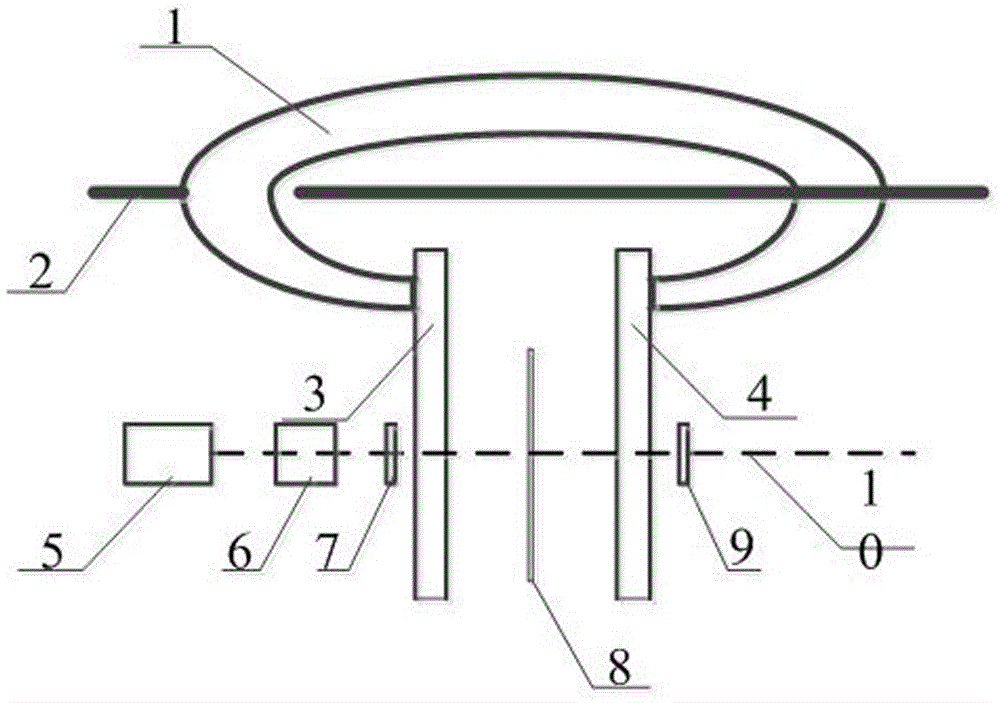
[0019] The present invention provides a linear optical current sensor through the optical line, such as figure 1 As shown, it includes: a light source 5, a collimator 6, a polarizer 7, a first magnetically conductive plate 3, a magneto-optical film 8, a second magnetically conductive plate 4, and a radial analyzer 9 arranged on the same optical path in sequence , to form a straight-through optical path; the first magnetically conductive plate 3 is arranged on one side of the air gap opening of the magnetic collecting ring 1 with an air gap, and the second magnetically conductive plate 4 is arranged on the side of the air gap opening of the magnetically collecting ring 1 The other side; also includes a current-carrying wire 2 passing through the magnet ring.

[0020] Further, in this embodiment, the air gap of the magnetic collecting ring...


PUM


Abstract

The invention relates to a straight optical path linear optical current sensor and a current detection method. The sensor comprises a light source, a collimator, a polarizer, a first magnetic conduction plate, a magneto optical film, a second magnetic conduction plate and a radial polarization grating. The first magnetic conduction plate is arranged at one side of an air gapped ferromagnetic concentrator ring air gap opening, and the second magnetic conduction plate is arranged at the other side of the ferromagnetic concentrator ring air gap opening. The sensor also comprises a current-carrying wire which goes through a ferromagnetic concentrator ring. The detection method comprises the steps that: a light signal from the light source passes the collimator, the polarizer, the first magnetic conduction plate, the magneto optical film and the second magnetic conduction plate to reaches the radial polarization grating, a light spot with a fixed shaped is obtained by radial polarization, and through measuring the rotation angle of the light spot, the current value to be measured in the current-carrying wire is obtained. According to the device and the method of the invention, the reflection phase shift is eliminated, the measurement sensitivity is increased, the detection mode is independent of optical power, and the ranges and sensitivity of linear measurement and dynamic measurement are improved greatly.

Description

technical field [0001] The invention relates to a straight-through optical line linear optical current sensor and a current detection method. Background technique [0002] Optical current transformers are mainly divided into two categories: all-fiber type and hybrid type: the former uses optical fibers for light transmission and sensing, and the latter uses optical fibers for light transmission, magneto-optical crystals for sensing, magneto-optical glass or magneto-optical films and other magnetic materials. light material. Among them, the sensing structure of the hybrid optical current transformer is mostly a magnetic collecting type, and optical devices such as prisms, polarizers, and magneto-optical materials are placed in the air gap of the iron core, so the air gap must be large enough. However, the large air gap affects the magnetic collection performance and makes the volume of the sensing head too large. The incident prism and reflective prism in the optical path i...

Claims


Application Information

Patent Timeline
Patent Type & Authority Applications(China)
IPC IPC(8): G01R15/24G01R19/25G01R19/00
CPCG01R15/246G01R19/0061G01R19/0092G01R19/25
Inventor 徐启峰黄奕钒项宇锴许志坤
Owner FUZHOU UNIV
Why Eureka
Try Eureka